82 minutes
Ansible for Networking - Part 3: Cisco IOS
The third part of my ongoing series of posts on Ansible for Networking will cover Cisco IOS. You can view the other posts in the series below: -
- Part 1 - Start of the series
- Part 2 - The Lab Environment
- Part 4 - Juniper JunOS
- Part 5 - Arista EOS
- Part 6 - MikroTik RouterOS
- Part 7 - VyOS
All the playbooks, roles and variables used in this article are available in my Network Automation with Ansible repository
Why IOS?
Anyone who has worked in the network industry long enough will have encountered Cisco equipment at some point in their career. Protocols from MPLS to VRRP all originated in some way from Cisco.
My networking career (like many others) started with Cisco IOS, and it is still the platform I am most familiar with.
Cisco offer a number of different operating systems, depending on the kit you are using. These include NX-OS (for the Nexus line of data centre switching), IOS-XR (geared more towards service provider equipment) and the ASA platform (for security). Cisco IOS is the most well-known, and probably the most deployed to this day.
It’s also worth mentioning IOS-XE. IOS-XE is Cisco IOS, but with a better software architecture.
IOS is monolithic, in that it uses a single software process for everything (from routing to authentication), meaning a bug in NTP could taken down your routing daemons.
IOS-XE has an improved architecture. It is separated into multiple different software processes, isolating the blast radius of failures. However if you administer IOS-XE devices, you’ll notice that the CLI is almost identical to IOS. If you can work with IOS, you can work with IOS-XE.
Objectives
For each vendor, I will be using Ansible to configure two routers/switches/firewalls/appliances.
One will serve as the Edge router, connecting to the Internet and also via BGP to the Net Server. The Net Server is a CentOS 8 Virtual Machine acting as a route server, syslog collector and TACACS+ server (detailed in The Lab Environment)
The other will be an internal router, performing core functions (i.e. internal routing rather than external).
Edge router
The edge router will run the following: -
- External BGP (eBGP) to the Net Server
- Advertising internal networks
- Internal BGP (iBGP) to the Internal router
- Advertising any routes received from the Net Server
- Advertising a default route (for internet access)
- OSPF
- Advertising loopbacks and internal networks between both routers
- IPv4 and IPv6 routing
- Using OSPFv3 (for IPv6 support)
- Using the IPv6 Address Family for BGP
- SNMPv3 for monitoring
- IPv4 NAT to allow internet access
- I cannot run IPv6 for internet access, as my current ISP does not support IPv6
- Logging via Syslog to the Net Server
- Authentication, Authorization and Accounting (AAA) via TACACS+ to the Net Server
- Access Lists on the port facing the Net Server
Usually you would also place some form of access-list or other filtering on your ports facing the internet, but this is in a lab environment and already behind a firewall.
Internal router
The internal router runs a subset of the functions that the edge router does: -
- Internal BGP (iBGP) to the Edge router
- Receiving any routes received from the Net Server
- Receiving a default route (for internet access)
- OSPF
- Advertising loopbacks and internal networks between both routers
- IPv4 and IPv6 routing
- Using OSPFv3 (for IPv6 support)
- Using the IPv6 Address Family for BGP
- SNMPv3 for monitoring
- Logging via Syslog to the Net Server
- Authentication, Authorization and Accounting (AAA) via TACACS+ to the Net Server
Ansible Network Automation
When managing a server with Ansible (whether Linux, BSD, Windows, or otherwise), it is often done remotely over SSH (or WinRM for Windows). You also need a user on the host that has the appropriate privileges to make the changes that are detailed in your Ansible playbooks.
It is important to note that while Ansible is agentless (i.e. it does not require the installation of a dedicated agent/daemon on the destination machine), it does assume an installation of Python to run the tasks (or Powershell, in the case of Windows).
In the case of network kit, there is no guarantee Python would be installed. In fact in many cases (Cisco IOS being one of them), your access is limited to the vendor-provided command line interface (CLI).
To overcome this, Ansible can use a “connection plugin” (the method that Ansible will use to connect to a destination host) called network_cli. This is baked directly into Ansible itself, rather than requiring the installation of additional plugins.
network_cli?
Ansible’s most used connection plugin is the ssh plugin, which will make changes to the destination host over a standard SSH connection. The network_cli plugin differs in a number of ways.
The Ansible modules run on the control host (i.e. where Ansible runs from) rather than directly on the destination host. You probably wouldn’t notice the difference in most of your tasks. Where this does make a difference is when using template or copy. These would either copy a file directly to the destination host, or generate a file from the provided template on the destination host. If you try and do this with the network_cli plugin, you’ll find the file on your Ansible control host, rather than the destination.
When Ansible requires privilege escalation, you use the become option. This allows Ansible to use sudo (or doas) to make changes that require elevated privileges. When using network_cli, an additional method is available called enable. “Enable” mode is equivalent to sudo on network devices, allowing elevated privileges and the ability to configure and change the destination host.
Finally, Ansible modules are platform-specific. For example, the ios_bgp would not work on a Fortinet device. While there are some modules that only work on some platforms (the firewalld module is not going to work OpenBSD for example), most Linux and *nix-based operating systems support the standard copy, template, file and many other common modules.
The network_cli plugin still uses SSH to connect to the destination devices, so if you already manage your devices with SSH, moving to Ansible instead requires no additional firewall/access changes.
Other connection plugins
While most of the network modules support network_cli, some of them use the netconf plugin instead (which is XML over SSH, rather than the CLI over SSH). This is not the case with any of the Cisco IOS modules I have used, but when I cover Juniper’s JunOS, this will be required.
Prerequisites
To be able to manage a Cisco IOS device with Ansible, some steps are required to allow access to the routers, and also some changes to the default Ansible connection configuration is required.
Ansible Configuration
The following defaults are required to use Ansible with Cisco IOS: -
ansible_user: ansible
ansible_connection: network_cli
ansible_network_os: ios
ansible_ssh_pass: ###REDACTED###
ansible_become: yes
ansible_become_method: enable
ansible_become_password: ###REDACTED###
The ansible_user and ansible_become options are no different than when managing a server or server(s). The additional options are: -
ansible_connection- The connection plugin used to connect to the devices (network_cliin this case)ansible_network_os- For a list of supported network operating systems, see hereansible_ssh_pass- Cisco IOS does support public key authentication, but few places (in my experience) use itansible_become_method- Usesenablefor privileged accessansible_become_password-enablemode requires another password (unless your TACACS+ server supports putting the user directly inenablemode on login), so this is supplied here
As you will likely need to store passwords, it would be best to use Ansible Vault to store them (more information on this the previous post in this series)
Cisco IOS Configuration
The prerequisites for allowing Ansible access to manage an IOS device are: -
- Create a user with the correct privilege level
- Create an
enablepassword - Give the device a
hostnameanddomain name(SSH will not generate keys on IOS without adomain name) - Enable SSH access
- Generate an SSH key on the device
Below shows how to do all of the following: -
cisco> enable
cisco# conf t
Enter configuration commands, one per line.  End with CNTL/Z.

! Add service password-encryption so that passwords are not shown in plain-text in the configuration
cisco(config)# service password-encryption

! Add the ansible user - Privilege level 15 is equivalent to full admin rights
cisco(config)# username ansible privilege 15 password 0 $PASSWORD-HERE$

! Create the enable password
cisco(config)# enable secret 0 $ENABLE-PASSWORD$

! Give the device a hostname
cisco(config)# hostname cisco-01

! Give the device a domain name
cisco-01(config)# ip domain name stubob.lab

! Enable SSH Access
cisco-01(config)# line vty 0 4         <---- Allows 5 remote users at once
cisco-01(config-line)# transport input ssh <--- Allows SSH, disables telnet
cisco-01(config-line)# exit
cisco-01(config)# ip ssh version 2

! Generate SSH key - Using RSA and a modulus of 2048 (change these to suit your needs/environment)
cisco-01(config)# crypto key generate rsa modulus 2048
% The key modulus size is 2048 bits
% Generating 2048 bit RSA keys, keys will be non-exportable...
[OK] (elapsed time was 0 seconds)

cisco-01(config)# end

! Write your configuration - Important, otherwise you will lose it if the devices powers off or reboots
cisco-01# copy running-config startup-config
Once the above is done, add the device into your Ansible inventory. My inventory file looks like the below: -
[ios]
cisco-01 ansible_host=10.15.30.23
cisco-02 ansible_host=10.15.30.24
By putting in a name as the “inventory hostname”, but supplying the IP as the ansible_host, I can refer to the devices by their name in my Playbooks and tasks, but without necessarily requiring it to match DNS.
Verification
Can we contact both devices?
$ ansible ios -m ios_facts | grep -i hostname
        "ansible_net_hostname": "cisco-02",
        "ansible_net_hostname": "cisco-01",
That will do it!
Another quirk of the network_cli connection plugin is that if you just use the ping module for testing (i.e. ansible all -m ping), it is actually the Ansible control host responding, not the routers themselves. Using the ios_facts module forces facts to be retrieved from the destination hosts instead (proving connectivity).
Setup
Below is a quick diagram of the setup: -
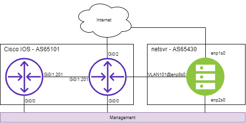
I covered the hypervisor network setup in the previous part of this series, but for quick explanation: -
- Internet access is via the default KVM NAT bridge
- Management is via an isolated KVM bridge
- Inter-device communication is done via VLANs, tagged over a KVM bridge
Using VLANs allows me to to forgo provisioning new interfaces or reconfigure existing ones to work with different kit. It also means that if and when I decide to run all of the vendors together, all the interfaces still exist.
VLANs, IP addressing and Autonomous System numbers
All of the VLANs, IPs and AS numbers are formed from an arbitrary ID, which I assign per vendor to make the addressing/configuration unique. My reasoning for this are explained in Part 2.
The ID chosen for Cisco IOS is 01.
VLANs
The VLANs used will be: -
- VLAN101 between the edge router and netsvr-01
- VLAN201 between the edge router and internal router
IP Addressing
- IPv4 Subnet on VLAN101:
10.100.101.0/24- edge router -
10.100.101.253/24 - netsvr-01 -
10.100.101.254/24
- edge router -
- IPv4 Subnet on VLAN201: 10.100.201.0/24
- edge router -
10.100.201.254/24 - internal router -
10.100.201.253/24
- edge router -
- IPv6 Subnet on VLAN101:
2001:db8:101::/64- edge router -
2001:db8:101::f/64 - netsvr-01 -
2001:db8:101:ffff/64
- edge router -
- IPv6 Subnet on VLAN201: 2001:db8:201::/64
- edge router -
2001:db8:201::a/64 - internal router -
2001:db8:201:f/64
- edge router -
- IPv4 Loopback Addressing
- edge router -
192.0.2.101/32 - internal router -
192.0.2.201/32
- edge router -
- IPv6 Loopback Address
- edge router -
2001:db8:901:beef::1/128 - internal router -
2001:db8:901:beef::2/128
- edge router -
BGP Autonomous System
The BGP Autonomous System number will be AS65101.
Configuration
Now we have covered the prerequisites, and assigned all of our network information, we can now work on making changes to the routers.
System tasks
This role covers tasks that affect the system itself, rather than anything like routing or management. For this lab, I update the banners (what you would see when logging into the device, or changing modes), enabling logging to a syslog server, and also enabling password encryption (so that passwords are not stored in clear text in the configuration).
To do this, I have created an Ansible role called system, and placed it in my roles directory: -
$ tree
├── ansible.cfg
├── ansible.log
├── group_vars
│   └── ios
├── host_vars
│   ├── cisco-01.yml
│   └── cisco-02.yml
├── inventory
├── ios.yaml
└── roles
    └── system
        ├── defaults
        │   └── main.yml
        ├── files
        ├── handlers
        │   └── main.yml
        ├── meta
        │   └── main.yml
        ├── README.md
        ├── tasks
        │   └── main.yml
        ├── templates
        ├── tests
        │   ├── inventory
        │   └── test.yml
        └── vars
            └── main.yml
The role is created by running ansible-galaxy init system, which creates a common directory structure and base files to update/replace as you need.
I’d like to thank Jon Spriggs for pointing out that Ansible will automatically look for roles in a roles/ directory. Previously all my roles were in the parent directory. This is a much cleaner way of separating them out!
Playbook
The contents of the Playbook can be seen below: -
---
## tasks file for system
- name: Remove unneeded banners
  ios_banner:
    banner: "{{ item }}"
    state: absent
  loop:
  - motd
  - exec
  - incoming

- name: Update login banner
  ios_banner:
    banner: login
    text: |
      ----------------------------------------
      |
      | This banner was generated by Ansible
      |
      ----------------------------------------
      |
      | You are logged into {{ inventory_hostname }}
      |
      ----------------------------------------
    state: present

- name: Configure syslog
  ios_logging:
    dest: host
    name: "{{ log_host }}"
    state: present

- name: Configure log buffer
  ios_logging:
    dest: buffered
    level: informational
    state: present

- name: Enable service password-encryption
  ios_config:
    lines:
      - service password-encryption
This playbook achieves the following: -
Removing unneeded banners
Ansible module: ios_banner
The first task removes the motd, exec and incoming banners (if any are set). I tend to only use login banners, so this is more personal preference.
Update the login banner
Ansible module: ios_banner
The pipe after text allows multiline freeform text. You can also supply a template file instead, rather than placing all of this in a Playbook. Using a template would be useful in scenarios where you have a specific banner provided by your legal department.
The {{ inventory_hostname }} is an Ansible in-built variable, that matches the name defined in your Ansible inventory. In my case, these are cisco-01 and cisco-02.
Now if you login to the device, you would see this: -
$ ssh [email protected]

----------------------------------------
|
| This banner was generated by Ansible
|
----------------------------------------
|
| You are logged into cisco-02
|
----------------------------------------
Password:
Configure syslog
Ansible module: ios_logging
This task configures logging to syslog, using a variable called log_host. This variable is defined in my group_vars file: -
$ cat group_vars/ios | grep -i log
log_host: 10.100.101.254
In the IOS configuration, this creates: -
logging host 10.100.101.254
Configure Log Buffer
Ansible module: ios_logging
This task adds local logging on the device, so you can run show log on a device and see any relevant and/or important events (e.g. BGP session resets, interface status changes etc)
In the IOS configuration, this creates: -
logging buffered 4096 informational
Enabling password encryption
Ansible module: ios_config
This stops passwords in the configuration file being viewed as plain text. As you can see, this uses the ios_config module.
The ios_config module
When an Ansible module doesn’t already exist, you can use ios_config to supply configuration extracts instead. For example, in the above there is no module for enabling different IOS “services”. This can be everything from the password-encryption module, to tcp-keepalive-in (i.e. enabling keepalives for inbound TCP sessions).
You have multiple options for how you can use ios_config. You can use the line option to specify the lines to be added, directly in the playbook. Alternatively you can use a template file (specifying src: $FILENAME rather than lines).
This makes some of the tasks less portable than others. If you decide you want to move to another vendor for your network, rather than simply targeting different modules (e.g. Arista’s eos_bgp rather than Cisco’s ios_bgp), you have to recreate full configuration snippets using the correct vendor syntax instead.
During this article (and further posts in the series) you’ll see what modules are already available, and what you will need to recreate yourself with the ios_config module.
Interfaces
The next role will configure all the interfaces on each device. This includes interface naming/descriptions, IP addressing, creation of sub-interfaces (i.e. those that use VLANs), and enable the interfaces. It also creates Loopback interfaces, so that our routing protocols can have consistent (and unique) identifiers, and allows routing not tied to a specific physical interface.
The role was created in the roles directory, using ansible-galaxy init interfaces.
Playbook
The contents of the Playbook are: -
---
## tasks file for interfaces
- name: Configure sub-interfaces first
  ios_config:
    src: subints.j2

- name: Configure interfaces - Status and Descriptions
  ios_interfaces:
    config:
      - name: "{{ item.ios_if }}"
        description: "{{ item.desc }}"
        enabled: "{{ item.enabled }}"
  loop: "{{ interfaces }}"

- name: Configure interfaces - L3 IPv4
  ios_l3_interfaces:
    config:
      - name: "{{ item.ios_if }}"
        ipv4:
        - address: "{{ item.ipv4 }}"
  when: item.ipv4 is defined
  loop: "{{ interfaces }}"

- name: Configure interfaces - L3 IPv6
  ios_l3_interfaces:
    config:
      - name: "{{ item.ios_if }}"
        ipv6:
        - address: "{{ item.ipv6 }}"
  when: item.ipv6 is defined
  loop: "{{ interfaces }}"
Each task will be explained in the following sections.
Configuring sub-interfaces
Ansible module: ios_config
Currently, no IOS interface module (either ios_interfaces, ios_l2_interfaces or ios_l3_interfaces) support sub-interfaces. If you are configuring a switch, there are multiple IOS-based VLAN modules that can achieve this, but none of the modules for routers fully support sub-interfaces.
Confusingly, all the IOS modules mentioned can update descriptions, add IP addressing and enable the interfaces. However what they cannot do is set the encapsulation of the interface, which is required to allow a sub-interface to use VLANs.
The template file itself is in roles/interfaces/templates/, and looks like the below: -
{% for interface in interfaces %}
{% if interface['subint'] is defined %}
{% for vlan in interface['subint']['vlans'] %}
interface {{ interface['ios_if'] }}.{{ vlan }}
 encapsulation dot1q {{ vlan }}
{% endfor %}
{% endif %}
{% endfor %}
To explain how this works, each router has a host-vars file specified (host_vars/$HOSTNAME.yaml). The contents for the interfaces section looks like: -
interfaces:
  - ios_if: "GigabitEthernet0/0"
    desc: "Management"
    enabled: true
    ipv4: "10.15.30.23/24"
  - ios_if: "GigabitEthernet0/1"
    desc: "VLAN Bridge"
    enabled: true
    subint:
      vlans:
      - 101
      - 201
  - ios_if: "GigabitEthernet0/1.101"
    desc: "To netsvr"
    enabled: true
    ipv4: "10.100.101.253/24"
    ipv6: "2001:db8:101::f/64"
  - ios_if: "GigabitEthernet0/1.201"
    desc: "To cisco-02"
    enabled: true
    ipv4: "10.100.201.254/24"
    ipv6: "2001:db8:201::a/64"
  - ios_if: "GigabitEthernet0/2"
    desc: "To the Internet"
    enabled: true
    ipv4: "dhcp"
  - ios_if: "loopback0"
    desc: "Loopback"
    enabled: true
    ipv4: "192.0.2.101/32"
    ipv6: "2001:db8:901:beef::1/128"
The above is a list of dictionaries (or array of maps, depending on your chosen nomenclature). When building the template, Ansible will load this list, and then loop through the contents. The logic for each interface in the list is: -
- If there is a field called “subint”, then…
- Create sub-interfaces, with the syntax
interface $interface-name.$vlan - Add the line
encapsulation dot1q $vlanto enable VLAN tagging
In the above scenario, this generates: -
interface Gi0/1.101
 encapsulation dot1q 101
interface Gi0/1.201
 encapsulation dot1q 201
After this, the other interface modules (ios_interfaces and ios_l3_interfaces) can change descriptions, add IP addressing and enable these sub-interfaces.
Status and descriptions
Ansible module: ios_interfaces
This task updates the description, and sets the status of the interfaces. The loop is used so that the task is applied to all interfaces in the aforementioned list (sourced from host_vars). The configuration that is generated by the above on the edge router (cisco-01) looks like the below: -
interface Loopback0
 description Loopback

interface GigabitEthernet0/0
 description Management

interface GigabitEthernet0/1
 description VLAN Bridge

interface GigabitEthernet0/1.101
 description To netsvr

interface GigabitEthernet0/1.201
 description To cisco-02

interface GigabitEthernet0/2
 description To the Internet
If you changed the enabled variable on one of the interfaces to false, you would also get: -
interface Gi0/2
 description To the internet
 shutdown
IPv4 addressing
Ansible module: ios_l3_interfaces
This task applies an IPv4 address to each interface (where enabled). As part of the task, we are using the when clause: -
  when: item.ipv4 is defined <----
  loop: "{{ interfaces }}"
It is important that this comes before you define your loop, and not after it. If you place the when clause after the loop, you will likely get an error that the variable item is not defined. item is Ansible’s in-built variable that it uses for each element in a loop.
By doing this, any interface which has the field ipv4 will have an IPv4 address added. The configuration generated by this is below: -
interface Loopback0
 ip address 192.0.2.101 255.255.255.255

interface GigabitEthernet0/0
 ip address 10.15.30.23 255.255.255.0

interface GigabitEthernet0/1
 no ip address

interface GigabitEthernet0/1.101
 ip address 10.100.101.253 255.255.255.0

interface GigabitEthernet0/1.201
 ip address 10.100.201.254 255.255.255.0

interface GigabitEthernet0/2
 ip address dhcp
There are three points to mention here: -
- Cisco IOS does not support the CIDR (i.e.
X.X.X.X/Y) format of IP addressing, instead requiring full subnet masks- Thankfully, the Ansible module already translates CIDR-formatted addressing to IP and subnet mask format
- You can supply the
dhcpword as an IPv4 address, rather than requiring different syntax for running the interface as a DHCP client - The interface
GigabitEthernet0/1does not have an IP address, so theno ip addressline is the default configuration for a Layer 3 interface
IPv6 addressing
Ansible module: ios_l3_interfaces
Similar to the IPv4 addressing task, this applies IPv6 addressing to all interfaces it is defined for. The only major differences are that we are looking for the ipv6 field in our interface list, rather than ipv4, and that we specify the ipv6 clause in our task to apply the address.
You could combine applying IPv4 and IPv6 addressing into a single task, but this would also require logic to say whether both are required, or if only one of IPv4 and IPv6 is required. I personally felt being a bit more verbose in the playbook makes it a bit easier to read (and thus easier to debug if required).
The resulting configuration is as such: -
interface Loopback0
 ipv6 address 2001:DB8:901:BEEF::1/128

interface GigabitEthernet0/0

interface GigabitEthernet0/1

interface GigabitEthernet0/1.101
 ipv6 address 2001:DB8:101::F/64

interface GigabitEthernet0/1.201
 ipv6 address 2001:DB8:201::A/64
As you can see, because IPv6 addressing is not added to every interface, some interfaces show nothing. This is to be expected, as IPv6 addressing is not expected by default in Cisco IOS.
Caveats
There is an odd quirk I have found with these tasks, specifically related to configuring Loopback interfaces. For whatever reason, when using the ios_l3_interfaces module, it will not actually apply configuration to a loopback if the name starts with an uppercase L (e.g. Loopback0 or Loopback2001). Instead, it needs to supplied as all lowercase (see the above host_vars, where the ios_if field for the loopback is loopback0 rather than Loopback0).
Unfortunately this means that other modules that rely on the interface name using an uppercase L (because they are matching against lines in the running configuration, which will always display it with an uppercase L) will register changes (even though the only difference is the casing).
Another point to note is that if you want your tasks to idempotent (i.e. where a task can be applied multiple times without making changes, other than on the initial application), you need to specify the interface names in full.
For those who are used to typing int Gi0/1 to make changes to GigabitEthernet0/1, you’ll need to break that habit when writing your playbooks and variables.
Verification
All of this means nothing if it doesn’t work, so I’ll show some basic tests to confirm everything works as expected
cisco-01
! Show IPs
cisco-01#show ip int brief
Interface                  IP-Address      OK? Method Status                Protocol
GigabitEthernet0/0         10.15.30.23     YES NVRAM  up                    up
GigabitEthernet0/1         unassigned      YES NVRAM  up                    up
GigabitEthernet0/1.101     10.100.101.253  YES NVRAM  up                    up
GigabitEthernet0/1.201     10.100.201.254  YES NVRAM  up                    up
GigabitEthernet0/2         192.168.122.86  YES DHCP   up                    up
Loopback0                  192.0.2.101     YES NVRAM  up                    up

cisco-01#show ipv6 int brief
GigabitEthernet0/0     [up/up]
    unassigned
GigabitEthernet0/1     [up/up]
    unassigned
GigabitEthernet0/1.101 [up/up]
    FE80::5054:FF:FEDD:4D5C
    2001:DB8:101::F
GigabitEthernet0/1.201 [up/up]
    FE80::5054:FF:FEDD:4D5C
    2001:DB8:201::A
GigabitEthernet0/2     [up/up]
    unassigned
Loopback0              [up/up]
    FE80::5054:FF:FE64:DD2A
    2001:DB8:901:BEEF::1


! Show interface statuses and descriptions
cisco-01#show int description
Interface                      Status         Protocol Description
Gi0/0                          up             up       Management
Gi0/1                          up             up       VLAN Bridge
Gi0/1.101                      up             up       To netsvr
Gi0/1.201                      up             up       To cisco-02
Gi0/2                          up             up       To the Internet
Lo0                            up             up       Loopback

! Ping to netsvr-01 on IPv4 and IPv6

cisco-01#ping 10.100.101.254
Type escape sequence to abort.
Sending 5, 100-byte ICMP Echos to 10.100.101.254, timeout is 2 seconds:
!!!!!

cisco-01#ping 2001:db8:101::ffff
Type escape sequence to abort.
Sending 5, 100-byte ICMP Echos to 2001:DB8:101::FFFF, timeout is 2 seconds:
!!!!!
Success rate is 100 percent (5/5), round-trip min/avg/max = 1/1/1 ms

! Ping to cisco-02 on IPv4 and IPv6
cisco-01#ping 10.100.201.253
Type escape sequence to abort.
Sending 5, 100-byte ICMP Echos to 10.100.201.253, timeout is 2 seconds:
!!!!!
Success rate is 100 percent (5/5), round-trip min/avg/max = 1/1/2 ms

cisco-01#ping 2001:db8:201::f
Type escape sequence to abort.
Sending 5, 100-byte ICMP Echos to 2001:DB8:201::F, timeout is 2 seconds:
!!!!!
Success rate is 100 percent (5/5), round-trip min/avg/max = 1/1/4 ms
cisco-02
! Show IPs
cisco-02#show ip int brief
Interface                  IP-Address      OK? Method Status                Protocol
GigabitEthernet0/0         10.15.30.24     YES NVRAM  up                    up
GigabitEthernet0/1         unassigned      YES NVRAM  up                    up
GigabitEthernet0/1.201     10.100.201.253  YES NVRAM  up                    up
Loopback0                  192.0.2.201     YES NVRAM  up                    up

cisco-02#show ipv6 int brief
GigabitEthernet0/0     [up/up]
    unassigned
GigabitEthernet0/1     [up/up]
    unassigned
GigabitEthernet0/1.201 [up/up]
    FE80::5054:FF:FE3A:2C40
    2001:DB8:201::F
Loopback0              [up/up]
    FE80::5054:FF:FE89:5EBB
    2001:DB8:901:BEEF::2

! Show interface statuses and descriptions
cisco-02#show int desc
Interface                      Status         Protocol Description
Gi0/0                          up             up       Management
Gi0/1                          up             up       VLAN Bridge
Gi0/1.201                      up             up       To cisco-01
Lo0                            up             up       Loopback

! Ping to cisco-01 on IPv4 and IPv6
cisco-02#ping 10.100.201.254
Type escape sequence to abort.
Sending 5, 100-byte ICMP Echos to 10.100.201.254, timeout is 2 seconds:
!!!!!
Success rate is 100 percent (5/5), round-trip min/avg/max = 1/1/2 ms

cisco-02#ping 2001:db8:201::a
Type escape sequence to abort.
Sending 5, 100-byte ICMP Echos to 2001:DB8:201::A, timeout is 2 seconds:
!!!!!
Success rate is 100 percent (5/5), round-trip min/avg/max = 1/1/2 ms
We will not be able to ping between the loopbacks yet, as we do not have routing in place. This will all be covered in the next section.
Routing
For routing, we are using BGP, OSPF and OSPFv3. As noted, BGP will be used between the edge router and netsvr-01 for, advertising internal networks to the Route Server running on netsvr-01. We’ll also receive the loopback address of netsvr-01 (192.0.2.1/32). We’ll also use BGP between the edge router and the internal router to advertise networks received from netsvr-01
We’ll use OSPF (for IPv4) and OSPFv3 (for IPv6) to advertise the internal networks between the edge router and internal router. These networks will be redistributed into BGP on the edge router, to allow them to be advertised to the netsvr-01.
Finally, we’ll advertise a default route from the edge router to the internal router, to allow the internal router to access the internet.
The role is created using ansible-galaxy init routing in the roles directory.
Main Playbook
The main playbook looks like the below: -
---
## tasks file for routing
##
- name: Include OSPF routing
  include: ospf.yml

- name: Include OSPFv3 routing
  include: ospfv3.yml

- name: Include BGP routing
  include: bgp.yml
There aren’t many tasks here, but thats because I have separated out OSPF, OSPFv3 and BGP into their own playbooks, and include them as part of the main playbook. This helps for readability of the individual playbooks, rather than one big playbook with lots of tasks.
OSPF Playbook
The OSPF playbook itself looks like: -
---
## tasks file for routing
##
- name: OSPF Process
  ios_config:
    lines:
      - "router ospf 1"

- name: OSPF Process - Router ID
  ios_config:
    lines:
      - "router-id {{ router_id }}"
    parents: router ospf 1

- name: OSPF Interfaces
  ios_config:
    lines:
      - ip ospf 1 area {{ item.ospf.area }}
    parents: interface {{ item.ios_if }}
  when: item.ospf is defined
  loop: "{{ interfaces }}"

- name: OSPF Interfaces - Passive
  ios_config:
    lines:
      - passive-interface {{ item.ios_if }}
    parents: router ospf 1
  when:
    - item.ospf is defined
    - item.ospf.passive is defined
  loop: "{{ interfaces }}"
Unfortunately, no Ansible modules currently exist for OSPF, so all of the configuration is applied using the ios_config module.
OSPF Process
Ansible module: ios_config
This task just enables OSPF, using process ID 1.
This generates the configuration: -
router ospf 1
Router ID
Ansible module: ios_config
The Router ID task picks up the router_id variable from host_vars, and applies it as part of the OSPF configuration. So for example, on cisco-02 (the internal router), this would generate: -
router ospf 1
 router-id 192.0.2.201
Parents?
An option of the ios_config module we haven’t seen yet is the parents option. With Cisco, configuration is done hierarchically. To enable some options, you have to enter another hierarchy level before the configuration will apply. In this case, you can’t supply the OSPF router ID without entering the router ospf 1 hierarchy level first.
The parent option is evaluated sequentially, so for multiple levels of hierarchy, you need to specify them in order. An example would be: -
router bgp 65101
 address-family ipv4 unicast
  neighbor 10.100.101.254 activate
The syntax that would achieve this is: -
- ios_config:
    lines:
      - neighbor 10.100.101.254
    parents:
      - router bgp 65101
      - address-family ipv4 unicast
OSPF Interfaces
Ansible module: ios_config
Similar to the Interfaces role, this section will scan through our list of interfaces (sourced from our host_vars per router), and if it finds the ospf field, it will enable OSPF on the interface. The OSPF area is also defined in our host_vars: -
  - ios_if: "GigabitEthernet0/1.201"
    desc: "To cisco-01"
    enabled: true
    ipv4: "10.100.201.253/24"
    ipv6: "2001:db8:201::f/64"
    ospf:
      area: "0.0.0.0"
  - ios_if: "loopback0"
    desc: "Loopback"
    enabled: true
    ipv4: "192.0.2.201/32"
    ipv6: "2001:db8:901:beef::2/128"
    ospf:
      area: "0.0.0.0"
This would generate the following configuration: -
interface Gi0/1.201
 ip ospf 1 area 0.0.0.0

interface Loopback0
 ip ospf 1 area 0.0.0.0
OSPF Interfaces - Passive
Ansible module: ios_config
This is similar to the OSPF interfaces role, except it also adds the Passive option. A passive interface in OSPF is one that has its IPv4 addressing (and subsequent IPv4 route/prefix) included in OSPF, but doesn’t attempt to form any OSPF neighbourships over it.
I won’t get too far down the rabbit hole of how OSPF works, but this is preferred over redistributing connected networks, because of how OSPF deals with routes received from other protocols.
It is possible for routers in a network to inform others to flush their “external” routes (i.e. those received from another protocol), even on the router that originated said routes. A weird issue with Quagga refreshing routes when NTP synchronized (i.e. when a server reboots…) taking down core MPLS in a previous role taught me that!
In this task, we have two when clauses. If they are specified like below (i.e. as a list in YAML syntax), AND logic is used (all criteria must be specified, rather than one or more of the criteria): -
  when:
    - item.ospf is defined
    - item.ospf.passive is defined
Again, we source the statements from our host_vars, looping through the interface list: -
  - ios_if: "GigabitEthernet0/1.201"
    desc: "To cisco-01"
    enabled: true
    ipv4: "10.100.201.253/24"
    ipv6: "2001:db8:201::f/64"
    ospf:
      area: "0.0.0.0"
  - ios_if: "loopback0"
    desc: "Loopback"
    enabled: true
    ipv4: "192.0.2.201/32"
    ipv6: "2001:db8:901:beef::2/128"
    ospf:
      area: "0.0.0.0"
      passive: true
The above host_vars would generate: -
interface Gi0/1.201
 ip ospf 1 area 0.0.0.0

interface Loopback0
 ip ospf 1 area 0.0.0.0

router ospf 1
 passive-interface Loopback0
As noted before, we need to use the parent option to place the passive-interface $INTERFACE under router ospf 1 in the configuration.
Verification
After this, we should be able to see OSPF routes, and we should be able to ping between the loopbacks on the edge router and the internal router
cisco-01
! Show OSPF interfaces
cisco-01#show ip ospf interface brief
Interface    PID   Area            IP Address/Mask    Cost  State Nbrs F/C
Lo0          1     0.0.0.0         192.0.2.101/32     1     LOOP  0/0
Gi0/1.201    1     0.0.0.0         10.100.201.254/24  1     BDR   1/1
Gi0/1.101    1     0.0.0.0         10.100.101.253/24  1     DR    0/0

! Show OSPF neighbours
cisco-01#show ip ospf neighbor

Neighbor ID     Pri   State           Dead Time   Address         Interface
192.0.2.201       1   FULL/DR         00:00:38    10.100.201.253  GigabitEthernet0/1.201

! Show routing table
cisco-01#show ip route ospf
Codes: L - local, C - connected, S - static, R - RIP, M - mobile, B - BGP
       D - EIGRP, EX - EIGRP external, O - OSPF, IA - OSPF inter area
       N1 - OSPF NSSA external type 1, N2 - OSPF NSSA external type 2
       E1 - OSPF external type 1, E2 - OSPF external type 2
       i - IS-IS, su - IS-IS summary, L1 - IS-IS level-1, L2 - IS-IS level-2
       ia - IS-IS inter area, * - candidate default, U - per-user static route
       o - ODR, P - periodic downloaded static route, H - NHRP, l - LISP
       a - application route
       + - replicated route, % - next hop override, p - overrides from PfR

Gateway of last resort is 192.168.122.1 to network 0.0.0.0

      192.0.2.0/32 is subnetted, 3 subnets
O        192.0.2.201
           [110/2] via 10.100.201.253, 03:51:43, GigabitEthernet0/1.201

! Ping!
cisco-01#ping 192.0.2.201
Type escape sequence to abort.
Sending 5, 100-byte ICMP Echos to 192.0.2.201, timeout is 2 seconds:
!!!!!
Success rate is 100 percent (5/5), round-trip min/avg/max = 1/1/1 ms

cisco-01#ping 192.0.2.201 source 192.0.2.101
Type escape sequence to abort.
Sending 5, 100-byte ICMP Echos to 192.0.2.201, timeout is 2 seconds:
Packet sent with a source address of 192.0.2.101
!!!!!
Success rate is 100 percent (5/5), round-trip min/avg/max = 1/1/2 ms
cisco-02
! Show OSPF interfaces
cisco-02#show ip ospf interface brief
Interface    PID   Area            IP Address/Mask    Cost  State Nbrs F/C
Lo0          1     0.0.0.0         192.0.2.201/32     1     LOOP  0/0
Gi0/1.201    1     0.0.0.0         10.100.201.253/24  1     DR    1/1

! Show OSPF neighbours
cisco-02#show ip ospf neighbor

Neighbor ID     Pri   State           Dead Time   Address         Interface
192.0.2.101       1   FULL/BDR        00:00:35    10.100.201.254  GigabitEthernet0/1.201

! Show routing table
cisco-02#show ip route ospf
Codes: L - local, C - connected, S - static, R - RIP, M - mobile, B - BGP
       D - EIGRP, EX - EIGRP external, O - OSPF, IA - OSPF inter area
       N1 - OSPF NSSA external type 1, N2 - OSPF NSSA external type 2
       E1 - OSPF external type 1, E2 - OSPF external type 2
       i - IS-IS, su - IS-IS summary, L1 - IS-IS level-1, L2 - IS-IS level-2
       ia - IS-IS inter area, * - candidate default, U - per-user static route
       o - ODR, P - periodic downloaded static route, H - NHRP, l - LISP
       a - application route
       + - replicated route, % - next hop override, p - overrides from PfR

Gateway of last resort is 192.0.2.101 to network 0.0.0.0

      10.0.0.0/8 is variably subnetted, 5 subnets, 2 masks
O        10.100.101.0/24
           [110/2] via 10.100.201.254, 04:43:48, GigabitEthernet0/1.201
      192.0.2.0/32 is subnetted, 3 subnets
O        192.0.2.101
           [110/2] via 10.100.201.254, 04:43:48, GigabitEthernet0/1.201

! Ping!
cisco-02#ping 192.0.2.101
Type escape sequence to abort.
Sending 5, 100-byte ICMP Echos to 192.0.2.101, timeout is 2 seconds:
!!!!!
Success rate is 100 percent (5/5), round-trip min/avg/max = 1/1/2 ms

cisco-02#ping 192.0.2.101 source lo0
Type escape sequence to abort.
Sending 5, 100-byte ICMP Echos to 192.0.2.101, timeout is 2 seconds:
Packet sent with a source address of 192.0.2.201
!!!!!
Success rate is 100 percent (5/5), round-trip min/avg/max = 1/1/2 ms

cisco-02#ping 10.100.101.253 source lo0
Type escape sequence to abort.
Sending 5, 100-byte ICMP Echos to 10.100.101.253, timeout is 2 seconds:
Packet sent with a source address of 192.0.2.201
!!!!!
Success rate is 100 percent (5/5), round-trip min/avg/max = 1/2/5 ms
All looking good to me!
OSPFv3 Playbook
OSPFv3 is a newer version of OSPF that supports IPv6. It also technically supports IPv4 as well, but not all implementations of OSPFv3 enable this feature. In the case of IOS, this feature does exist in more recent versions, but did not in older versions.
I will only use it for IPv6, so that those managing routers without the address family feature in OSPFv3 are still able to make use of these playbooks.
The playbook for OSPFv3 is very similar to the OSPF playbook, except for one key difference: -
---
## tasks file for routing
##

- name: Enable IPv6 routing
  ios_config:
    lines:
      - "ipv6 unicast-routing"

- name: OSPFv3 Process
  ios_config:
    lines:
      - "router ospfv3 1"

- name: OSPFv3 Process - Router ID
  ios_config:
    lines:
      - "router-id {{ router_id }}"
    parents: router ospfv3 1

- name: OSPFv3 Interfaces
  ios_config:
    lines:
      - ipv6 ospf 1 area {{ item.ospfv3.area }}
    parents: interface {{ item.ios_if }}
  when: item.ospfv3 is defined
  loop: "{{ interfaces }}"

- name: OSPFv3 Interfaces - Passive
  ios_config:
    lines:
      - passive-interface {{ item.ios_if }}
    parents: router ospfv3 1
  when:
    - item.ospfv3 is defined
    - item.ospfv3.passive is defined
  loop: "{{ interfaces }}"

- name: Removed IPv4 address family
  ios_config:
    lines:
      - "no address-family ipv4 unicast"
    parents: router ospfv3 1
The first task in this playbook enables ipv6 unicast-routing. IOS by default (or at least the version I am working in this lab) does not have this enabled this out of the box, meaning that any attempts to add IPv6 routing protocols will fail.
The final task also removes the IPv4 unicast address family. If you are wanting to run both IPv4 and IPv6 with OSPFv3, you can remove this task.
Other than that, the playbook is almost identical to the OSPF playbook, except using the word ipv6 where ip is used before, and ospfv3 where router ospfv3 where router ospf was used before.
The host_vars used to generate this are: -
interfaces:
  - ios_if: "GigabitEthernet0/0"
    desc: "Management"
    enabled: true
    ipv4: "10.15.30.23/24"
  - ios_if: "GigabitEthernet0/1"
    desc: "VLAN Bridge"
    enabled: true
    subint:
      vlans:
      - 101
      - 201
  - ios_if: "GigabitEthernet0/1.101"
    desc: "To netsvr"
    enabled: true
    ipv4: "10.100.101.253/24"
    ipv6: "2001:db8:101::f/64"
    ospf:
      area: "0.0.0.0"
      passive: true
    ospfv3:
      area: "0.0.0.0"
      passive: true
  - ios_if: "GigabitEthernet0/1.201"
    desc: "To cisco-02"
    enabled: true
    ipv4: "10.100.201.254/24"
    ipv6: "2001:db8:201::a/64"
    ospf:
      area: "0.0.0.0"
    ospfv3:
      area: "0.0.0.0"
  - ios_if: "GigabitEthernet0/2"
    desc: "To the Internet"
    enabled: true
    ipv4: "dhcp"
  - ios_if: "loopback0"
    desc: "Loopback"
    enabled: true
    ipv4: "192.0.2.101/32"
    ipv6: "2001:db8:901:beef::1/128"
    ospf:
      area: "0.0.0.0"
      passive: true
    ospfv3:
      area: "0.0.0.0"
      passive: true
As can be seen here, for every interface we want OSPFv3 to run on, we add the ospfv3 sections. We specify what area they are in, and also add the passive variable if the interfaces are not used for forming OSPF neighbours.
The generated configuration for the above would be: -
ipv6 unicast-routing

interface Loopback0
 ipv6 address 2001:DB8:901:BEEF::1/128
 ipv6 ospf 1 area 0.0.0.0

interface GigabitEthernet0/1.101
 ipv6 ospf 1 area 0.0.0.0

interface GigabitEthernet0/1.201
 ipv6 ospf 1 area 0.0.0.0

router ospfv3 1
 address-family ipv6 unicast
  passive-interface GigabitEthernet0/1.101
  passive-interface Loopback0
 exit-address-family
Verification
After this, we should be able to see OSPFv3 routes, and we should be able to ping between the loopbacks on the edge router and the internal router
cisco-01
! Show OSPF interfaces
cisco-01#show ipv6 ospf interface brief
Interface    PID   Area            Intf ID    Cost  State Nbrs F/C
Lo0          1     0.0.0.0         8          1     LOOP  0/0
Gi0/1.201    1     0.0.0.0         10         1     BDR   1/1
Gi0/1.101    1     0.0.0.0         9          1     DR    0/0

! Show OSPF neighbours
cisco-01#show ipv6 ospf neighbor

            OSPFv3 Router with ID (192.0.2.101) (Process ID 1)

Neighbor ID     Pri   State           Dead Time   Interface ID    Interface
192.0.2.201       1   FULL/DR         00:00:35    8               GigabitEthernet0/1.201

! Show routing table
cisco-01#show ipv6 route ospf
IPv6 Routing Table - default - 8 entries
Codes: C - Connected, L - Local, S - Static, U - Per-user Static route
       B - BGP, HA - Home Agent, MR - Mobile Router, R - RIP
       H - NHRP, I1 - ISIS L1, I2 - ISIS L2, IA - ISIS interarea
       IS - ISIS summary, D - EIGRP, EX - EIGRP external, NM - NEMO
       ND - ND Default, NDp - ND Prefix, DCE - Destination, NDr - Redirect
       RL - RPL, O - OSPF Intra, OI - OSPF Inter, OE1 - OSPF ext 1
       OE2 - OSPF ext 2, ON1 - OSPF NSSA ext 1, ON2 - OSPF NSSA ext 2
       la - LISP alt, lr - LISP site-registrations, ld - LISP dyn-eid
       lA - LISP away, a - Application
O   2001:DB8:901:BEEF::2/128 [110/1]
     via FE80::5054:FF:FE3A:2C40, GigabitEthernet0/1.201

! Ping!
cisco-01#ping 2001:db8:901:beef::2
Type escape sequence to abort.
Sending 5, 100-byte ICMP Echos to 2001:DB8:901:BEEF::2, timeout is 2 seconds:
!!!!!
Success rate is 100 percent (5/5), round-trip min/avg/max = 1/1/1 ms

cisco-01#ping 2001:db8:901:beef::2 source lo0
Type escape sequence to abort.
Sending 5, 100-byte ICMP Echos to 2001:DB8:901:BEEF::2, timeout is 2 seconds:
Packet sent with a source address of 2001:DB8:901:BEEF::1
!!!!!
Success rate is 100 percent (5/5), round-trip min/avg/max = 1/1/2 ms
cisco-02
! Show OSPF interfaces
cisco-02#show ipv6 ospf interface brief
Interface    PID   Area            Intf ID    Cost  State Nbrs F/C
Lo0          1     0.0.0.0         7          1     LOOP  0/0
Gi0/1.201    1     0.0.0.0         8          1     DR    1/1

! Show OSPF neighbours
cisco-02#show ipv6 ospf neighbor

            OSPFv3 Router with ID (192.0.2.201) (Process ID 1)

Neighbor ID     Pri   State           Dead Time   Interface ID    Interface
192.0.2.101       1   FULL/BDR        00:00:32    10              GigabitEthernet0/1.201

! Show routing table
cisco-02#show ipv6 route ospf
IPv6 Routing Table - default - 7 entries
Codes: C - Connected, L - Local, S - Static, U - Per-user Static route
       B - BGP, HA - Home Agent, MR - Mobile Router, R - RIP
       H - NHRP, I1 - ISIS L1, I2 - ISIS L2, IA - ISIS interarea
       IS - ISIS summary, D - EIGRP, EX - EIGRP external, NM - NEMO
       ND - ND Default, NDp - ND Prefix, DCE - Destination, NDr - Redirect
       RL - RPL, O - OSPF Intra, OI - OSPF Inter, OE1 - OSPF ext 1
       OE2 - OSPF ext 2, ON1 - OSPF NSSA ext 1, ON2 - OSPF NSSA ext 2
       la - LISP alt, lr - LISP site-registrations, ld - LISP dyn-eid
       lA - LISP away, a - Application
O   2001:DB8:101::/64 [110/2]
     via FE80::5054:FF:FEDD:4D5C, GigabitEthernet0/1.201
O   2001:DB8:901:BEEF::1/128 [110/1]
     via FE80::5054:FF:FEDD:4D5C, GigabitEthernet0/1.201

! Ping!
cisco-02#ping 2001:db8:901:beef::1
Type escape sequence to abort.
Sending 5, 100-byte ICMP Echos to 2001:DB8:901:BEEF::1, timeout is 2 seconds:
!!!!!
Success rate is 100 percent (5/5), round-trip min/avg/max = 1/1/4 ms

cisco-02#ping 2001:db8:901:beef::1 source lo0
Type escape sequence to abort.
Sending 5, 100-byte ICMP Echos to 2001:DB8:901:BEEF::1, timeout is 2 seconds:
Packet sent with a source address of 2001:DB8:901:BEEF::2
!!!!!
Success rate is 100 percent (5/5), round-trip min/avg/max = 1/2/5 ms

cisco-02#ping 2001:db8:101::f
Type escape sequence to abort.
Sending 5, 100-byte ICMP Echos to 2001:DB8:101::F, timeout is 2 seconds:
!!!!!
Success rate is 100 percent (5/5), round-trip min/avg/max = 1/1/4 ms
This all looks good!
BGP Playbook
The BGP playbook is where the most complex logic is used. However we also get to make use of native Ansible modules, so some of this logic can carry over when configuring other vendors in future.
The full playbook looks like so: -
---
## tasks file for routing
##
- name: Configure BGP - eBGP v4 peers
  ios_bgp:
    config:
      bgp_as: "{{ bgp['local_as'] }}"
      log_neighbor_changes: True
      router_id: "{{ router_id }}"
      neighbors:
      - neighbor: "{{ item.peer }}"
        remote_as: "{{ item.remote_as }}"
  when:
    - bgp is defined
    - bgp.neighbors is defined
    - bgp.neighbors.ipv4 is defined
    - item.ebgp is defined
  loop: "{{ bgp.neighbors.ipv4 }}"
  tags:
  - bgp
  - bgp_v4

- name: Configure BGP - eBGP v6 peers
  ios_bgp:
    config:
      bgp_as: "{{ bgp['local_as'] }}"
      log_neighbor_changes: True
      router_id: "{{ router_id }}"
      neighbors:
      - neighbor: "{{ item.peer }}"
        remote_as: "{{ item.remote_as }}"
      address_family:
        - afi: ipv6
          neighbors:
          - neighbor: "{{ item.peer }}"
            activate: true
  when:
    - bgp is defined
    - bgp.neighbors is defined
    - bgp.neighbors.ipv6 is defined
    - item.ebgp is defined
  loop: "{{ bgp.neighbors.ipv6 }}"
  tags:
  - bgp
  - bgp_v6

- name: Configure BGP - iBGP v4 peers
  ios_bgp:
    config:
      bgp_as: "{{ bgp['local_as'] }}"
      log_neighbor_changes: True
      router_id: "{{ router_id }}"
      neighbors:
      - neighbor: "{{ item.peer }}"
        remote_as: "{{ item.remote_as }}"
        update_source: "{{ item.update_source }}"
  when:
    - bgp is defined
    - bgp.neighbors is defined
    - bgp.neighbors.ipv4 is defined
    - item.ibgp is defined
  loop: "{{ bgp.neighbors.ipv4 }}"
  tags:
  - bgp
  - bgp_v4

- name: Configure BGP - iBGP v6 peers
  ios_bgp:
    config:
      bgp_as: "{{ bgp['local_as'] }}"
      log_neighbor_changes: True
      router_id: "{{ router_id }}"
      neighbors:
      - neighbor: "{{ item.peer }}"
        remote_as: "{{ item.remote_as }}"
        update_source: "{{ item.update_source }}"
      address_family:
        - afi: ipv6
          neighbors:
          - neighbor: "{{ item.peer }}"
            activate: true
  when:
    - bgp is defined
    - bgp.neighbors is defined
    - bgp.neighbors.ipv6 is defined
    - item.ibgp is defined
  loop: "{{ bgp.neighbors.ipv6 }}"
  tags:
  - bgp
  - bgp_v6

- name: Configure BGP - Redistribute OSPF
  ios_bgp:
    config:
      bgp_as: "{{ bgp['local_as'] }}"
      address_family:
        - afi: ipv4
          redistribute:
            - protocol: ospf
              id: 1
  when:
    - bgp is defined
    - bgp.redist is defined
    - bgp.redist.ospf is defined
  tags:
  - bgp
  - bgp_v4

- name: Configure BGP - Redistribute OSPFv3
  ios_bgp:
    config:
      bgp_as: "{{ bgp['local_as'] }}"
      address_family:
        - afi: ipv6
          redistribute:
            - protocol: ospf
              id: 1
  when:
    - bgp is defined
    - bgp.redist is defined
    - bgp.redist.ospfv3 is defined
  tags:
  - bgp
  - bgp_v6

- name: Configure BGP - iBGP v4 Default Originate
  ios_config:
    lines:
      - neighbor {{ item.peer }} default-originate
    parents:
      - router bgp {{ bgp['local_as'] }}
      - address-family ipv4 unicast
  when:
    - bgp is defined
    - bgp.neighbors is defined
    - bgp.neighbors.ipv4 is defined
    - item.ibgp is defined
    - item.default_originate is defined
  loop: "{{ bgp.neighbors.ipv4 }}"
  tags:
  - bgp
  - bgp_v4
There is a lot going on here, however most of the tasks are very similar, with slight updates based upon whether they are external BGP or internal BGP, and also whether they are IPv4 or IPv6.
Rather than dissecting every single play, I will go through the first of each kind (i.e. adding peers, redistribution) and then mention the differences for the subsequent tasks.
Configuring eBGP IPv4 peers
Ansible module: ios_bgp
Unlike the OSPF playbooks, Ansible has a BGP module for Cisco IOS, so all of the tasks (bar one) use this module.
As per the previous playbooks, the host specific variables are sourced from host_vars. In this case, they are used to define BGP peering: -
router_id: 192.0.2.101
bgp:
  local_as: 65101
  redist:
    ospf: true
    ospfv3: true
  neighbors:
    ipv4:
     - peer: 10.100.101.254
       remote_as: 65430
       ebgp: true
     - peer: 192.0.2.201
       remote_as: 65101
       ibgp: true
       update_source: Loopback0
       default_originate: true
    ipv6:
     - peer: "2001:db8:101::ffff"
       remote_as: 65430
       ebgp: true
     - peer: "2001:db8:901:beef::2"
       remote_as: 65101
       ibgp: true
       update_source: Loopback0
As there’s quite a lot going on in this, I shall go through each part separately.
- name: Configure BGP - eBGP v4 peers
  ios_bgp:
    config:
      bgp_as: "{{ bgp['local_as'] }}"
      log_neighbor_changes: True
      router_id: "{{ router_id }}"
In this section, we are retrieving the Local Autonomous System number (i.e the AS number of this host) and applying it. We also add the log_neighbor_changes option, so that any BGP neighbour changes are sent to syslog, local logging, and to the console.
Finally, we set the router_id to the Router ID variable in host_vars. This is not strictly required, but the whole idea behind having a set router ID is for ease of troubleshooting, rather than one that can change if interface IPs change (or go down).
      neighbors:
      - neighbor: "{{ item.peer }}"
        remote_as: "{{ item.remote_as }}"
The neighbours themselves are built using a list defined in our host_vars. As the neighbors option allows multiple peers to be defined, this is the perfect use case of Ansible loops.
  when:
    - bgp is defined
    - bgp.neighbors is defined
    - bgp.neighbors.ipv4 is defined
    - item.ebgp is defined
The conditional logic here states that this task will run if: -
- The
bgpvariable is defined (which comes fromhost_varsin our case AND - The
bgpvariable has a section calledneighborsAND - The
bgp.neighborssection has a section calledipv4AND - The
itemvariable has theebgpfield
The item variable comes from the following loop: -
loop: "{{ bgp.neighbors.ipv4 }}"
This loop goes through our list of neighbours, and if they have IPv4, it adds BGP peers based upon this.
The configuration generated is below: -
router bgp 65101
 bgp router-id 192.0.2.101
 bgp log-neighbor-changes
 neighbor 10.100.101.254 remote-as 65430
 !
 address-family ipv4
  neighbor 10.100.101.254 activate
 exit-address-family
 !
As a bonus, I have also added the tags section, which allows you to target tasks with specific tags when running your playbook.
To run only BGP tasks, you would run ansible-playbook ios.yaml --tags bgp. To run only BGP tasks that are for IPv4, you would run ansible-playbook ios.yaml --tags bgp_v4. This makes it easier to target only the changes you want, as well as testing changes to tasks in Playbooks.
Configuring eBGP IPv6 peers
Ansible module: ios_bgp
This task is very similar to the task for building external BGP peers for IPv4, but with some extra options.
      address_family:
        - afi: ipv6
          neighbors:
          - neighbor: "{{ item.peer }}"
            activate: true
This section is required to enable BGP for IPv6 peering. The reason behind this is that by default, Cisco will only enable IPv4 peering by default. If you do not add this, your peers will be configured, but they won’t attempt to form peering sessions over IPv6.
Otherwise, the only notable changes are that we are looking for whether bgp.neighbors.ipv6 is in our when section, our loop is over the list of peers in bgp.neighbors.ipv6, and we have a tag of bgp_v6.
The configuration this will generate is below: -
router bgp 65101
 bgp router-id 192.0.2.101
 bgp log-neighbor-changes
 neighbor 2001:DB8:101::FFFF remote-as 65430
 !
 address-family ipv4
  no neighbor 2001:DB8:101::FFFF activate
 exit-address-family
 !
 address-family ipv6
  neighbor 2001:DB8:101::FFFF activate
 exit-address-family
It is worth noting that we are reapplying the BGP router ID and the logging of neighbour changes. This is required, because if we only have a IPv6 sessions, this would be the only task that runs, thus meaning no other task would create the Router ID and add the neighbour change logging.
Configuring iBGP IPv4 peers
Ansible module: ios_bgp
The major difference between the eBGP and iBGP configuration is that we also add the update_source parameter. Typically, external BGP sessions are formed over a WAN link to a provider, whereas internal BGP sessions form over a core network.
You are more likely to have multiple links to each BGP-speaking device in your core network than to external providers, therefore you do not want your BGP session to only work over a specific interface. Instead, if you use an IP that is routable over multiple interfaces (e.g. a loopback IP) your BGP sessions can still form when interfaces go down.
If you do not specify an update_source, your BGP sessions will usually be sourced from the IP of the outgoing interface. Changing the update_source to be a loopback address addresses this.
If you recall from the OSPF section, we are using OSPF to advertise our loopback IPs between the edge and internal router. This gives us reachability between the loopback addresses of the routers.
Other than the above, the only other changes is that we are expecting to see the ibgp: true statement in our host_vars for a peer.
The generated configuration is below: -
router bgp 65101
 bgp router-id 192.0.2.101
 bgp log-neighbor-changes
 neighbor 192.0.2.201 remote-as 65101
 neighbor 192.0.2.201 update-source Loopback0
 !
 address-family ipv4
  neighbor 192.0.2.201 activate
 exit-address-family
Configuring IBGP IPv6 peers
Ansible module: ios_bgp
This changes in this task are effectively an amalgamation of what changes are required for eBGP IPv6 peers, and the update_source that we use for iBGP v4 peers
        update_source: "{{ item.update_source }}"
      address_family:
        - afi: ipv6
          neighbors:
          - neighbor: "{{ item.peer }}"
            activate: true
IPv6 iBGP peers also need activating in the IPv6 address family, to ensure that we attempt to form IPv6 peering. We also add the update_source to ensure that IPv6 peering stays up even if an interface were to go down.
Reachability of loopbacks uses OSPFv3 rather than OSPFv2, but this is necessary for IPv6.
The generated configuration is below: -
router bgp 65101
 bgp router-id 192.0.2.101
 bgp log-neighbor-changes
 neighbor 2001:DB8:901:BEEF::2 remote-as 65101
 neighbor 2001:DB8:901:BEEF::2 update-source Loopback0
 !
 address-family ipv4
  no neighbor 2001:DB8:901:BEEF::2 activate
 exit-address-family
 !
 address-family ipv6
  neighbor 2001:DB8:901:BEEF::2 activate
 exit-address-family
Configuring OSPF Redistribution for IPv4
Ansible module: ios_bgp
Redistribution is where you take routes discovered/generated by one routing protocol and export them to another. The reason you would do this is because typically your core network just needs reachability between other parts of the network, and either a default route or a subset of external routes for access to the internet and networks out of your control.
Also, core networks are usually built on Layer 3 switching. Nowadays switches can run routing protocols (including BGP), MPLS, Segment Routing, VxLAN and much more.
However, these switches usually have a limited amount of TCAM (Ternary Content-addressable memory), which is where routes and MAC address tables (among other things) are stored.
The Broadcom Trident range of chipsets are very popular in the network switching space, however up until recently they could only store around 16,000 IPv4 routes in TCAM. This poses a problem when using BGP, as the full BGP routing table is currently sitting around the 800,000 mark, which would overload the TCAM on these switches.
Using something like OSPF for reachability inside your network, and then using BGP on your edge routers (which are usually capable of storing many millions of routes) will avoid the need to run expensive routers for every hop in your network.
The following task achieves redistribution from OSPF to BGP: -
- name: Configure BGP - Redistribute OSPF
  ios_bgp:
    config:
      bgp_as: "{{ bgp['local_as'] }}"
      address_family:
        - afi: ipv4
          redistribute:
            - protocol: ospf
              id: 1
  when:
    - bgp is defined
    - bgp.redist is defined
    - bgp.redist.ospf is defined
  tags:
  - bgp
  - bgp_v4
The task has similar options to our other ios_bgp based tasks, but rather than defining multiple peers, we are defining (potentially) multiple protocols to redistribute. If we wanted to import our static routes, or we want to run IS-IS or EIGRP, you would just add them to the list like so: -
          redistribute:
            - protocol: eigrp
              id: 10
            - protocol: isis
            - protocol: static
The rest of the task is just to ensure it is defined under the correct BGP process (defined by our BGP AS number), and also to only apply it when: -
- If the
bgpvariable exists AND - If the
bgp.redistvariable exists AND - If the
bgp.redist.ospfvariable exists
The generated configuration is below: -
router bgp 65101
 !
 address-family ipv4
  redistribute ospf 1
 exit-address-family
Configuring OSPF Redistribution for IPv6
Ansible module: ios_bgp
Everything mentioned in regards to OSPF redistribution for IPv4 applies here, with the global IPv6 routing table often being larger than what networking switching can handle.
Otherwise, the only differences in the task are that we are targeting afi: ipv6 (i.e. the IPv6 address family) rather than IPv4, and that we are looking for the existence of bgp.redist.ospfv3.
The generated configuration is below: -
router bgp 65101
 !
 address-family ipv6
  redistribute ospf 1
 exit-address-family
Advertising a default route via BGP
Ansible module: ios_config
There are multiple ways to advertise a default route from BGP: -
- Receive one from an upstream BGP peer, and advertise it downstream
- Import one from another protocol (e.g. a static default route)
- Generate one on a per-peer basis
The latter is what we are going to do in this task. Unfortunately the option to do this is not in the ios_bgp module, so we use the ios_config module instead to achieve this: -
- name: Configure BGP - iBGP v4 Default Originate
  ios_config:
    lines:
      - neighbor {{ item.peer }} default-originate
    parents:
      - router bgp {{ bgp['local_as'] }}
      - address-family ipv4 unicast
  when:
    - bgp is defined
    - bgp.neighbors is defined
    - bgp.neighbors.ipv4 is defined
    - item.ibgp is defined
    - item.default_originate is defined
  loop: "{{ bgp.neighbors.ipv4 }}"
  tags:
  - bgp
  - bgp_v4
In this, we are going two levels into the configuration hierarchy. First, we enter router bgp $OUR-AS-NUMBER, then we enter address-family ipv4 unicast. From here, we can then apply the default-originate statement to our peer.
We only apply this to peers that have the default_originate option specified, and only if they are ibgp peers. As we are not functioning as a transit provider in this lab, we do not need to advertise default routes to external peers.
The generated configuration is below: -
router bgp 65101
 !
 address-family ipv4
  neighbor 192.0.2.201 default-originate
 exit-address-family
To verify that this works: -
cisco-01 Edge Router
cisco-01#show ip bgp neighbors 192.0.2.201 advertised-routes
BGP table version is 8, local router ID is 192.0.2.101
Status codes: s suppressed, d damped, h history, * valid, > best, i - internal,
              r RIB-failure, S Stale, m multipath, b backup-path, f RT-Filter,
              x best-external, a additional-path, c RIB-compressed,
Origin codes: i - IGP, e - EGP, ? - incomplete
RPKI validation codes: V valid, I invalid, N Not found

Originating default network 0.0.0.0  <--------------------------

     Network          Next Hop            Metric LocPrf Weight Path
 *>  10.100.101.0/24  0.0.0.0                  0         32768 ?
 *>  10.100.201.0/24  0.0.0.0                  0         32768 ?
 *>  192.0.2.1/32     10.100.101.254           0             0 65430 i
 *>  192.0.2.101/32   0.0.0.0                  0         32768 ?
 *>  192.0.2.201/32   10.100.201.253           2         32768 ?
cisco-02 Internal Router
cisco-02#show ip route bgp
Codes: L - local, C - connected, S - static, R - RIP, M - mobile, B - BGP
       D - EIGRP, EX - EIGRP external, O - OSPF, IA - OSPF inter area
       N1 - OSPF NSSA external type 1, N2 - OSPF NSSA external type 2
       E1 - OSPF external type 1, E2 - OSPF external type 2
       i - IS-IS, su - IS-IS summary, L1 - IS-IS level-1, L2 - IS-IS level-2
       ia - IS-IS inter area, * - candidate default, U - per-user static route
       o - ODR, P - periodic downloaded static route, H - NHRP, l - LISP
       a - application route
       + - replicated route, % - next hop override, p - overrides from PfR

Gateway of last resort is 192.0.2.101 to network 0.0.0.0 <---------------------

B*    0.0.0.0/0 [200/0] via 192.0.2.101, 01:00:45
      192.0.2.0/32 is subnetted, 3 subnets
B        192.0.2.1 [200/0] via 10.100.101.254, 01:00:45
We have a default route!
Verification
After all of the above has run, we should have BGP sessions up over IPv4 and IPv6, as well as routes received and sent to netsvr-01 BGP route server.
cisco-01
! Show BGP neighbours on IPv4 and IPv6
cisco-01#show bgp ipv4 unicast summary
BGP router identifier 192.0.2.101, local AS number 65101
BGP table version is 8, main routing table version 8
6 network entries using 864 bytes of memory
6 path entries using 480 bytes of memory
4/3 BGP path/bestpath attribute entries using 608 bytes of memory
1 BGP AS-PATH entries using 24 bytes of memory
0 BGP route-map cache entries using 0 bytes of memory
0 BGP filter-list cache entries using 0 bytes of memory
BGP using 1976 total bytes of memory
BGP activity 8/0 prefixes, 8/0 paths, scan interval 60 secs

Neighbor        V           AS MsgRcvd MsgSent   TblVer  InQ OutQ Up/Down  State/PfxRcd
10.100.101.254  4        65430     317     348        8    0    0 05:12:20        1
192.0.2.201     4        65101     345     350        8    0    0 05:11:39        0

cisco-01#show bgp ipv6 unicast summary
BGP router identifier 192.0.2.101, local AS number 65101
BGP table version is 17, main routing table version 17
2 network entries using 336 bytes of memory
2 path entries using 208 bytes of memory
2/2 BGP path/bestpath attribute entries using 304 bytes of memory
1 BGP AS-PATH entries using 24 bytes of memory
0 BGP route-map cache entries using 0 bytes of memory
0 BGP filter-list cache entries using 0 bytes of memory
BGP using 872 total bytes of memory
BGP activity 8/0 prefixes, 8/0 paths, scan interval 60 secs

Neighbor        V           AS MsgRcvd MsgSent   TblVer  InQ OutQ Up/Down  State/PfxRcd
2001:DB8:101::FFFF
                4        65430     316     349       17    0    0 05:12:18        1
2001:DB8:901:BEEF::2
                4        65101     344     359       17    0    0 05:11:40        0

! Show BGP routes
cisco-01#show bgp ipv4 unicast
BGP table version is 8, local router ID is 192.0.2.101
Status codes: s suppressed, d damped, h history, * valid, > best, i - internal,
              r RIB-failure, S Stale, m multipath, b backup-path, f RT-Filter,
              x best-external, a additional-path, c RIB-compressed,
Origin codes: i - IGP, e - EGP, ? - incomplete
RPKI validation codes: V valid, I invalid, N Not found

     Network          Next Hop            Metric LocPrf Weight Path
     0.0.0.0          0.0.0.0                                0 i
 *>  10.100.101.0/24  0.0.0.0                  0         32768 ?
 *>  10.100.201.0/24  0.0.0.0                  0         32768 ?
 *>  192.0.2.1/32     10.100.101.254           0             0 65430 i
 *>  192.0.2.101/32   0.0.0.0                  0         32768 ?
 *>  192.0.2.201/32   10.100.201.253           2         32768 ?

cisco-01#show bgp ipv6 unicast
BGP table version is 17, local router ID is 192.0.2.101
Status codes: s suppressed, d damped, h history, * valid, > best, i - internal,
              r RIB-failure, S Stale, m multipath, b backup-path, f RT-Filter,
              x best-external, a additional-path, c RIB-compressed,
Origin codes: i - IGP, e - EGP, ? - incomplete
RPKI validation codes: V valid, I invalid, N Not found

     Network          Next Hop            Metric LocPrf Weight Path
 *>  2001:DB8:901:BEEF::2/128
                       FE80::5054:FF:FE3A:2C40
                                                1         32768 ?
 *>  2001:DB8:999:BEEF::1/128
                       2001:DB8:101::FFFF
                                                0             0 65430 i

! Ping the netsvr Loopback (192.0.2.1 and 2001:DB8:999:BEEF::1)
cisco-01#ping 192.0.2.1
Type escape sequence to abort.
Sending 5, 100-byte ICMP Echos to 192.0.2.1, timeout is 2 seconds:
!!!!!
Success rate is 100 percent (5/5), round-trip min/avg/max = 1/1/1 ms

cisco-01#ping 192.0.2.1 source lo0
Type escape sequence to abort.
Sending 5, 100-byte ICMP Echos to 192.0.2.1, timeout is 2 seconds:
Packet sent with a source address of 192.0.2.101
!!!!!
Success rate is 100 percent (5/5), round-trip min/avg/max = 1/1/1 ms

cisco-01#ping 192.0.2.1 source Gi0/1.201
Type escape sequence to abort.
Sending 5, 100-byte ICMP Echos to 192.0.2.1, timeout is 2 seconds:
Packet sent with a source address of 10.100.201.254
!!!!!
Success rate is 100 percent (5/5), round-trip min/avg/max = 1/1/2 ms

cisco-01#ping 2001:db8:999:beef::1
Type escape sequence to abort.
Sending 5, 100-byte ICMP Echos to 2001:DB8:999:BEEF::1, timeout is 2 seconds:
!!!!!
Success rate is 100 percent (5/5), round-trip min/avg/max = 1/1/1 ms

cisco-01#ping 2001:db8:999:beef::1 source lo0
Type escape sequence to abort.
Sending 5, 100-byte ICMP Echos to 2001:DB8:999:BEEF::1, timeout is 2 seconds:
Packet sent with a source address of 2001:DB8:901:BEEF::1
.
Success rate is 0 percent (0/1)
cisco-02
! Show BGP neighbours on IPv4 and IPv6
cisco-02#show bgp ipv4 unicast summary
BGP router identifier 192.0.2.201, local AS number 65101
BGP table version is 6, main routing table version 6
5 network entries using 720 bytes of memory
5 path entries using 400 bytes of memory
3/3 BGP path/bestpath attribute entries using 456 bytes of memory
1 BGP AS-PATH entries using 24 bytes of memory
0 BGP route-map cache entries using 0 bytes of memory
0 BGP filter-list cache entries using 0 bytes of memory
BGP using 1600 total bytes of memory
BGP activity 7/0 prefixes, 7/0 paths, scan interval 60 secs

Neighbor        V           AS MsgRcvd MsgSent   TblVer  InQ OutQ Up/Down  State/PfxRcd
192.0.2.101     4        65101     361     355        6    0    0 05:20:43        5

cisco-02#show bgp ipv6 unicast summary
BGP router identifier 192.0.2.201, local AS number 65101
BGP table version is 3, main routing table version 3
2 network entries using 336 bytes of memory
2 path entries using 208 bytes of memory
2/2 BGP path/bestpath attribute entries using 304 bytes of memory
1 BGP AS-PATH entries using 24 bytes of memory
0 BGP route-map cache entries using 0 bytes of memory
0 BGP filter-list cache entries using 0 bytes of memory
BGP using 872 total bytes of memory
BGP activity 7/0 prefixes, 7/0 paths, scan interval 60 secs

Neighbor        V           AS MsgRcvd MsgSent   TblVer  InQ OutQ Up/Down  State/PfxRcd
2001:DB8:901:BEEF::1
                4        65101     370     354        3    0    0 05:20:52        2

! Show BGP routes
cisco-02#show bgp ipv4 unicast
BGP table version is 6, local router ID is 192.0.2.201
Status codes: s suppressed, d damped, h history, * valid, > best, i - internal,
              r RIB-failure, S Stale, m multipath, b backup-path, f RT-Filter,
              x best-external, a additional-path, c RIB-compressed,
Origin codes: i - IGP, e - EGP, ? - incomplete
RPKI validation codes: V valid, I invalid, N Not found

     Network          Next Hop            Metric LocPrf Weight Path
 *>i 0.0.0.0          192.0.2.101              0    100      0 i
 r>i 10.100.101.0/24  192.0.2.101              0    100      0 ?
 r>i 10.100.201.0/24  192.0.2.101              0    100      0 ?
 *>i 192.0.2.1/32     10.100.101.254           0    100      0 65430 i
 r>i 192.0.2.101/32   192.0.2.101              0    100      0 ?

cisco-02#show bgp ipv6 unicast
BGP table version is 3, local router ID is 192.0.2.201
Status codes: s suppressed, d damped, h history, * valid, > best, i - internal,
              r RIB-failure, S Stale, m multipath, b backup-path, f RT-Filter,
              x best-external, a additional-path, c RIB-compressed,
Origin codes: i - IGP, e - EGP, ? - incomplete
RPKI validation codes: V valid, I invalid, N Not found

     Network          Next Hop            Metric LocPrf Weight Path
 r>i 2001:DB8:901:BEEF::2/128
                       2001:DB8:901:BEEF::1
                                                1    100      0 ?
 *>i 2001:DB8:999:BEEF::1/128
                       2001:DB8:101::FFFF
                                                0    100      0 65430 i

! Ping the netsvr Loopback (192.0.2.1 and 2001:db8:999:beef::1)
cisco-02#ping 192.0.2.1
Type escape sequence to abort.
Sending 5, 100-byte ICMP Echos to 192.0.2.1, timeout is 2 seconds:
!!!!!
Success rate is 100 percent (5/5), round-trip min/avg/max = 1/2/4 ms

cisco-02#ping 192.0.2.1 source lo0
Type escape sequence to abort.
Sending 5, 100-byte ICMP Echos to 192.0.2.1, timeout is 2 seconds:
Packet sent with a source address of 192.0.2.201
!!!!!
Success rate is 100 percent (5/5), round-trip min/avg/max = 1/2/3 ms

cisco-02#ping 2001:db8:999:beef::1 source lo0
Type escape sequence to abort.
Sending 5, 100-byte ICMP Echos to 2001:DB8:999:BEEF::1, timeout is 2 seconds:
Packet sent with a source address of 2001:DB8:901:BEEF::2
!!!!!
Success rate is 100 percent (5/5), round-trip min/avg/max = 1/2/6 ms
Unfortunately, we can see that there are some reachability issues from cisco-01 to the loopback of the netsvr-01. The reason for this is because when you redistribute OSPFv3 into BGP, by default it will not include any connected networks (i.e. the routes that are local to the router itself).
This option can be enabled with redistribute ospf 1 include-connected, however it is not supported by the Ansible ios_bgp module as an argument. If you need to do this, you would need to change this section to use ios_config, and build the task so that it will apply exact configuration lines. A task like the following would achieve this: -
- name: Configure BGP - Redistribute OSPFv3 and include connected networks
  ios_config:
    lines:
      - redistribute ospf 1 include-connected
    parents:
      - router bgp {{ bgp['local_as'] }}
      - address-family ipv6 unicast
  when:
    - bgp is defined
    - bgp.redist is defined
    - bgp.redist.ospfv3 is defined
  tags:
  - bgp
  - bgp_v6
SNMP
Compare to the Routing section, this section will be fairly straightforward. The role is created the same way, ansible-galaxy init snmp in the roles directory.
There is no native Ansible module for enabling SNMP, so again we are using the ios_config module.
Playbook
The contents of the playbook are below: -
---
## tasks file for snmp
- name: Enable SNMPv3
  ios_config:
    src: snmpv3.j2
  tags:
    - snmp
As you can see, there’s only one task in this. We are picking up the snmpv3.j2 template, and applying it to the routers.
Template file
snmp-server location {{ snmp['location'] }}
snmp-server contact {{ snmp['contact'] }}
snmp-server group {{ snmp['group'] }} v3 priv
snmp-server user {{ snmp['user'] }} {{ snmp['group'] }} v3 auth sha {{ snmp['auth_key'] }} priv aes 128 {{ snmp['priv_key'] }}
All of the variables in this are sourced from group_vars, rather than host_vars, as the SNMP details will be common across both routers
group_vars
The contents of the group_vars file for this are: -
snmp:
  location: Yeti Home
  contact: The Hairy One
  user: yetiops
  group: yetiops_group
  auth_key: !vault |
            $ANSIBLE_VAULT;1.1;AES256
            383###REDACTED###############################################################566
            363###REDACTED###############################################################366
            343###REDACTED###############################################################565
            326###REDACTED###############################################################362
            3431
  priv_key: !vault |
            $ANSIBLE_VAULT;1.1;AES256
            386###REDACTED###############################################################764
            613###REDACTED###############################################################630
            646###REDACTED###############################################################331
            376###REDACTED###############################################################137
            3563
We are using Ansible Vault to store the keys, which I go into more detail how to use in Part 2
Applying the task
As the task has a tag, we can apply the role using the --tag argument when running our playbook. However as Ansible Vault is used, you’ll also need to use --ask-vault-pass (or one of the other methods for supply your Vault passwords) otherwise Ansible will not be able to decrypt the secrets.
$ ansible-playbook ios.yaml --tags snmp --ask-vault-pass
Vault password:

PLAY [ios] **********************************************************************************************************************************************

TASK [snmp : Enable SNMPv3] ******************************************************************************************************************************
changed: [cisco-02]
changed: [cisco-01]

PLAY RECAP ***********************************************************************************************************************************************
cisco-01                   : ok=1    changed=1    unreachable=0    failed=0    skipped=0    rescued=0    ignored=0
cisco-02                   : ok=1    changed=1    unreachable=0    failed=0    skipped=0    rescued=0    ignored=0
The generated configuration looks like the below: -
snmp-server group yetiops_group v3 priv
snmp-server location Yeti Home
snmp-server contact The Hairy One
It will also generate the line snmp-server user $USER $GROUP v3 auth sha $AUTH-KEY priv aes 128 $PRIV-KEY, but this will not appear in your configuration, due to the service password-encryption option specified earlier.
Verification
To check whether this is working, you will need either some form of monitoring system, or something like snmpwalk to check it: -
! snmpwalk to cisco-01
$ sudo snmpwalk -v3 -l authPriv -u yetiops -a SHA -A $AUTH-KEY -x AES -X $PRIV-KEY 192.0.2.101
SNMPv2-MIB::sysObjectID.0 = OID: SNMPv2-SMI::enterprises.9.1.1041
DISMAN-EVENT-MIB::sysUpTimeInstance = Timeticks: (2355886) 6:32:38.86
SNMPv2-MIB::sysContact.0 = STRING: The Hairy One
SNMPv2-MIB::sysName.0 = STRING: cisco-01.stubob.lab
SNMPv2-MIB::sysLocation.0 = STRING: Yeti Home
SNMPv2-MIB::sysServices.0 = INTEGER: 78
[...]

! snmpwalk to cisco-02
$ sudo snmpwalk -v3 -l authPriv -u yetiops -a SHA -A yeti_hash123 -x AES -X yeti_key123 192.0.2.201
SNMPv2-MIB::sysObjectID.0 = OID: SNMPv2-SMI::enterprises.9.1.1041
DISMAN-EVENT-MIB::sysUpTimeInstance = Timeticks: (2356123) 6:32:41.23
SNMPv2-MIB::sysContact.0 = STRING: The Hairy One
SNMPv2-MIB::sysName.0 = STRING: cisco-02.stubob.lab
SNMPv2-MIB::sysLocation.0 = STRING: Yeti Home
SNMPv2-MIB::sysServices.0 = INTEGER: 78
[...]
Looks like its working!
Access Lists
To limit what traffic can talk over our interface from the edge router to the netsvr-01 machine, we are going to use an Access List. Access Lists are stateless, meaning you have to match traffic in both directions, rather than just applying it one direction and the device matching return traffic.
The role is created with the name acl, ansible-galaxy init acl in the roles directory.
There is no native Ansible module for enabling Access Lists, so again we are using the ios_config module. Access lists are even provided as one of the examples for how to use ios_config module in IOS when you read the Ansible documentation.
Playbook
The playbook looks like the below: -
## tasks file for acl
- name: Edge Access List - Outbound IPv4
  ios_config:
    lines:
      - 10 permit icmp any any log
      - 20 permit udp any host {{ log_host }}  eq syslog log
      - 30 permit tcp any host {{ tacacs['ipv4'] }}  eq tacacs log
      - 1000 deny ip any any log
    parents:
      - ip access-list extended EDGE-OUT
  when:
    - rtr_role is search("edge")
  tags:
    - acl
    - acl_ipv4

- name: Edge Access List - Inbound IPv4
  ios_config:
    lines:
      - 10 permit icmp any any log
      - 20 permit tcp host {{ tacacs['ipv4'] }} eq tacacs any log
      - 1000 deny ip any any log
    parents:
      - ip access-list extended EDGE-IN
  when:
    - rtr_role is search("edge")
  tags:
    - acl
    - acl_ipv4

- name: Edge Access List - BGP Outbound IPv4
  ios_config:
    lines:
      - "{{ item.acl.acl_index }} permit tcp any host {{ item.peer }} eq bgp log"
    parents:
      - ip access-list extended EDGE-OUT
  when:
    - rtr_role is search("edge")
    - bgp is defined
    - bgp.neighbors is defined
    - bgp.neighbors.ipv4 is defined
    - item.acl is defined
  loop: "{{ bgp.neighbors.ipv4 }}"
  tags:
    - acl
    - acl_ipv4

- name: Edge Access List - BGP Inbound IPv4
  ios_config:
    lines:
      - "{{ item.acl.acl_index }} permit tcp host {{ item.peer }} eq bgp any log"
    parents:
      - ip access-list extended EDGE-IN
  when:
    - rtr_role is search("edge")
    - bgp is defined
    - bgp.neighbors is defined
    - bgp.neighbors.ipv4 is defined
    - item.acl is defined
  loop: "{{ bgp.neighbors.ipv4 }}"
  tags:
    - acl
    - acl_ipv4

- name: Apply Inbound IPv4 ACL
  ios_config:
    lines:
      - ip access-group {{ item.acl.ipv4.in }} in
    parents:
      - interface {{ item.ios_if }}
  when:
    - item.acl is defined
    - item.acl.ipv4 is defined
    - item.acl.ipv4.in is defined
  loop: "{{ interfaces }}"
  tags:
    - acl
    - acl_ipv4

- name: Apply Outbound IPv4 ACL
  ios_config:
    lines:
      - ip access-group {{ item.acl.ipv4.out }} out
    parents:
      - interface {{ item.ios_if }}
  when:
    - item.acl is defined
    - item.acl.ipv4 is defined
    - item.acl.ipv4.out is defined
  loop: "{{ interfaces }}"
  tags:
    - acl
    - acl_ipv4

- name: Edge Access List - Outbound IPv6
  ios_config:
    lines:
      - sequence 10 permit icmp any any log
      - sequence 1000 deny ipv6 any any log
    parents:
      - ipv6 access-list EDGEv6-OUT
  when:
    - rtr_role is search("edge")
  tags:
    - acl
    - acl_ipv6

- name: Edge Access List - Inbound IPv6
  ios_config:
    lines:
      - sequence 10 permit icmp any any log
      - sequence 1000 deny ipv6 any any log
    parents:
      - ipv6 access-list EDGEv6-IN
  when:
    - rtr_role is search("edge")
  tags:
    - acl
    - acl_ipv6

- name: Edge Access List - BGP Outbound IPv6
  ios_config:
    lines:
      - "sequence {{ item.acl.acl_index }} permit tcp any host {{ item.peer }} eq bgp log"
    parents:
      - ipv6 access-list EDGEv6-OUT
  when:
    - rtr_role is search("edge")
    - bgp is defined
    - bgp.neighbors is defined
    - bgp.neighbors.ipv6 is defined
    - item.acl is defined
  loop: "{{ bgp.neighbors.ipv6 }}"
  tags:
    - acl
    - acl_ipv6

- name: Edge Access List - BGP Inbound IPv6
  ios_config:
    lines:
      - "sequence {{ item.acl.acl_index }} permit tcp host {{ item.peer }} eq bgp any log"
    parents:
      - ipv6 access-list EDGEv6-IN
  when:
    - rtr_role is search("edge")
    - bgp is defined
    - bgp.neighbors is defined
    - bgp.neighbors.ipv6 is defined
    - item.acl is defined
  loop: "{{ bgp.neighbors.ipv6 }}"
  tags:
    - acl
    - acl_ipv6

- name: Apply Inbound IPv6 ACL
  ios_config:
    lines:
      - ipv6 traffic-filter {{ item.acl.ipv6.in }} in
    parents:
      - interface {{ item.ios_if }}
  when:
    - item.acl is defined
    - item.acl.ipv6 is defined
    - item.acl.ipv6.in is defined
  loop: "{{ interfaces }}"
  tags:
    - acl
    - acl_ipv6

- name: Apply Outbound IPv6 ACL
  ios_config:
    lines:
      - ipv6 traffic-filter {{ item.acl.ipv6.out }} out
    parents:
      - interface {{ item.ios_if }}
  when:
    - item.acl is defined
    - item.acl.ipv6 is defined
    - item.acl.ipv6.out is defined
  loop: "{{ interfaces }}"
  tags:
    - acl
    - acl_ipv6
To summarize what is being applied here: -
- Allow any ICMP traffic (including pings) inbound and outbound (IPv4 and IPv6)
- Allow syslog outbound (IPv4 only)
- Syslog is UDP, therefore no return rule is required
- Allow any eBGP peers to talk inbound and outbound (IPv4 and IPv6)
- Allow TACACS destined to and from the TACACS server (IPv4 only)
- Apply the access lists to our interfaces
Edge Access List - Outbound IPv4
Ansible module: ios_config
The module creates an access list called EDGE-OUT, and creates rules in this list for ICMP, syslog, TACACS+, and denies anything else. Each rule also includes the log keyword, so that we will get a log message for every time each rule is matched.
In a production scenario, you probably wouldn’t log every match, but this helps in a lab to ensure that every rule is being used appropriately.
The numbers at the start of each line are the sequence number, saying in what order each rule is evaluated. The reason for placing the final deny rule at the sequence number 1000 is so that we have enough space to add entries before the deny rules (up to 999), rather than having to carve out gaps, or deleting the deny rule and moving it (allowing all traffic through while doing so).
We pull the IP of the syslog server and TACACS+ server from our group_vars, and we also only apply this to the edge router (using the rtr_role variable, defined in the host_vars file).
group_vars
log_host: 10.100.101.254
tacacs:
  ipv4: 192.0.2.1
  secret: supersecret
edge (cisco-01) host_vars
router_id: 192.0.2.101
rtr_role: edge
The generated configuration from this is below: -
ip access-list extended EDGE-OUT
 permit icmp any any log
 permit udp any host 10.100.101.254 eq syslog log
 permit tcp any host 192.0.2.1 eq tacacs log
 deny   ip any any log
Unfortunately because we have to specify the sequence numbers, the task registers as changed every time you run it (in the running configuration on the router, the sequence numbers are not shown). If you have a fairly static access list, you could probably do away with the sequence numbers, but we will be adding dynamic elements to this list soon.
Edge Access List - Inbound IPv4
Ansible module: ios_config
This task is almost identical to the previous one, except that: -
- Syslog is UDP, so no return traffic is required
- Where we are matching specific IPs, they need to be matched as the source of traffic, not the destination
So rather than permit tcp any host {{ tacacs['ipv4'] }} eq tacacs log (which matches any source address, with a destination of the TACACS+ server), we instead have permit tcp host {{ tacacs['ipv4'] }} eq tacacs any log (which matches a source of TACACS+, to any destination IP).
The generated configuration is below: -
ip access-list extended EDGE-IN
 permit icmp any any log
 permit tcp host 192.0.2.1 eq tacacs any log
 deny   ip any any log
Edge Access List - BGP Outbound IPv4
Ansible module: ios_config
This task is where we start to add some “dynamic” elements, in that we could have 1 BGP peer, or we could have 50, but all would need to go in this access list. You might wonder when you would have that many peers over a single interface. If you are connected to any of the Internet Exchanges/Peering LANs (e.g. LINX, DE-CIX, AMS-IX), you might have 10s or 100s of peers over the same interface.
The task here looks for values in the host_vars file, and will apply when: -
- The
rtr_roleisedgeAND - The
bgpvariable exists AND - The
bgp.neighborsvariable exists AND - The
bgp.neighbors.ipv4variable exists AND - For each BGP peer, if the variable ACL Is defined
We loop through all of the peers we have defined to find whether the above conditions are true. We supply an acl_index number in the host_vars, to say where in our access list to place the configuration: -
rtr_role: edge
bgp:
  local_as: 65101
  redist:
    ospf: true
    ospfv3: true
  neighbors:
    ipv4:
     - peer: 10.100.101.254
       remote_as: 65430
       ebgp: true
       acl:
         acl_index: 110
     - peer: 192.0.2.201
       remote_as: 65101
       ibgp: true
       update_source: Loopback0
       default_originate: true
In the above, only the first peer has the acl variable defined. The configuration this will then generate is: -
ip access-list extended EDGE-OUT
 permit tcp any host 10.100.101.254 eq bgp log
With the rest of the access list, you would see the following: -
ip access-list extended EDGE-OUT
 permit icmp any any log
 permit udp any host 10.100.101.254 eq syslog log
 permit tcp any host 192.0.2.1 eq tacacs log
 permit tcp any host 10.100.101.254 eq bgp log
 deny   ip any any log
The reason that the BGP rule is before before the final deny rule is because we supplied an index number, to use as the sequence number in the access list. Without this, it would go after the deny rule.
Edge Access List - BGP Inbound IPv4
Ansible module: ios_config
This task is the same as the for the outbound IPv4 BGP task, except that the order of matching is reversed. Rather than having the BGP peer as the destination in the access list, in this task it is the source (because the traffic is being matched FROM the peer, not to it)
The resulting access list, using the same host_vars in the previous task, would be generated as: -
ip access-list extended EDGE-IN
 permit tcp host 10.100.101.254 eq bgp any log
The full access list would then be: -
ip access-list extended EDGE-IN
 permit icmp any any log
 permit tcp host 192.0.2.1 eq tacacs any log
 permit tcp host 10.100.101.254 eq bgp any log
 deny   ip any any log
Apply Inbound IPv4 ACL
Ansible module: ios_config
This task applies the access list to an interface. The interface (or interfaces) comes from our host_vars again: -
interfaces:
  - ios_if: "GigabitEthernet0/1.101"
    desc: "To netsvr"
    enabled: true
    ipv4: "10.100.101.253/24"
    ipv6: "2001:db8:101::f/64"
    acl:
      ipv4:
        in: EDGE-IN
        out: EDGE-OUT
      ipv6:
        in: EDGEv6-IN
        out: EDGEv6-OUT
    ospf:
      area: "0.0.0.0"
      passive: true
    ospfv3:
      area: "0.0.0.0"
      passive: true
As you can see here, with have our acl section, which specifies the name of our inbound Edge Access list. The task we are using looks for whether: -
- The
aclvariable is defined AND - The
acl.ipv4variable is defined AND - The
acl.ipv4.invariable is defined
This means that we can supply only an inbound access list, or only an outbound access list, or only IPv4, or only IPv6. We do not need to have all of them for the tasks to work.
In our host_vars, the only interface that has an acl is our interface to the netsvr-01 machine. The configuration that would be applied is: -
interface GigabitEthernet0/1.101
 ip access-group EDGE-IN in
In context with the other configuration: -
interface GigabitEthernet0/1.101
 description To netsvr
 encapsulation dot1Q 101
 ip address 10.100.101.253 255.255.255.0
 ip access-group EDGE-IN in
 ip ospf 1 area 0.0.0.0
 ipv6 address 2001:DB8:101::F/64
 ipv6 ospf 1 area 0.0.0.0
Apply Outbound IPv4 ACL
Ansible module: ios_config
This task is almost identical to the previous task, except it applies in the outbound direction. We are looking for the acl.ipv4.out variable in our interfaces defined in host_vars, and then applying the Access List defined.
Based upon the host_vars noted above, the resulting configuration would be: -
interface GigabitEthernet0/1.101
 ip access-group EDGE-OUT out
In context with the other configuration: -
interface GigabitEthernet0/1.101
 description To netsvr
 encapsulation dot1Q 101
 ip address 10.100.101.253 255.255.255.0
 ip access-group EDGE-IN in
 ip access-group EDGE-OUT out
 ip ospf 1 area 0.0.0.0
 ipv6 address 2001:DB8:101::F/64
 ipv6 ospf 1 area 0.0.0.0
IPv6 Access Lists
All of the following tasks after this are for applying access lists for IPv6. Everything is almost identical to IPv4, except for the following minor details: -
- You need to use the keyword
sequencebefore you use a sequence number- IPv4 -
permit icmp any any log - IPv6 -
sequence 10 permit icmp any any log
- IPv4 -
- IPv6 access lists are applied using the
traffic-filterkeyword rather thanaccess-group- IPv4 -
ip access-group EDGE-IN in - IPv6 -
ipv6 traffic-filter EDGEv6-IN in
- IPv4 -
You also need to name your access lists differently from your IPv4 access lists. If you use the same name IOS will raise an error, saying there is already an access list with the same name (despite the fact you are defining it for a different address type).
After all the tasks are applied, the following configuration is generated: -
interface GigabitEthernet0/1.101
 ipv6 traffic-filter EDGEv6-IN in
 ipv6 traffic-filter EDGEv6-OUT out

ipv6 access-list EDGEv6-IN
 sequence 10 permit icmp any any log
 sequence 110 permit tcp host 2001:DB8:101::FFFF eq bgp any log
 sequence 1000 deny ipv6 any any log

ipv6 access-list EDGEv6-OUT
 sequence 10 permit icmp any any log
 sequence 110 permit tcp any host 2001:DB8:101::FFFF eq bgp log
 sequence 1000 deny ipv6 any any log
When seen in context with our other configuration: -
interface GigabitEthernet0/1.101
 description To netsvr
 encapsulation dot1Q 101
 ip address 10.100.101.253 255.255.255.0
 ip access-group EDGE-IN in
 ip access-group EDGE-OUT out
 ip ospf 1 area 0.0.0.0
 ipv6 address 2001:DB8:101::F/64
 ipv6 traffic-filter EDGEv6-IN in
 ipv6 traffic-filter EDGEv6-OUT out
 ipv6 ospf 1 area 0.0.0.0

ipv6 access-list EDGEv6-IN
 sequence 10 permit icmp any any log
 sequence 110 permit tcp host 2001:DB8:101::FFFF eq bgp any log
 sequence 1000 deny ipv6 any any log

ipv6 access-list EDGEv6-OUT
 sequence 10 permit icmp any any log
 sequence 110 permit tcp any host 2001:DB8:101::FFFF eq bgp log
 sequence 1000 deny ipv6 any any log
Verification
We shall now verify that the access lists are working, and that they match traffic as intended: -
! Show access lists
cisco-01#           show ip access-lists
Extended IP access list EDGE-IN
    10 permit icmp any any log (52 matches)
    20 permit tcp host 192.0.2.1 eq tacacs any log (4089 matches)
    30 permit tcp host 10.100.101.254 eq bgp any log (3093 matches)
    40 deny ip any any log (7 matches)
Extended IP access list EDGE-OUT
    10 permit icmp any any log (25 matches)
    20 permit udp any host 10.100.101.254 eq syslog log (4 matches)
    30 permit tcp any host 192.0.2.1 eq tacacs log (768 matches)
    40 permit tcp any host 10.100.101.254 eq bgp log
    50 deny ip any any log

cisco-01#show ipv6 access-list
IPv6 access list EDGEv6-IN
    permit icmp any any log (4398 matches) sequence 10
    permit tcp host 2001:DB8:101::FFFF eq bgp any log (3115 matches) sequence 110
    deny ipv6 any any log sequence 1000
IPv6 access list EDGEv6-OUT
    permit icmp any any log (62 matches) sequence 10
    permit tcp any host 2001:DB8:101::FFFF eq bgp log sequence 110
    deny ipv6 any any log sequence 1000

! Are we logging traffic?
*Mar  4 07:52:19.002: %IPV6_ACL-6-ACCESSLOGDP: list EDGEv6-IN/10 permitted icmpv6 FE80::90AB:180D:BBD:92C0 -> FE80::5054:FF:FEDD:4D5C (136/0), 10 packets
*Mar  4 07:52:19.002: %IPV6_ACL-6-ACCESSLOGDP: list EDGEv6-IN/10 permitted icmpv6 FE80::90AB:180D:BBD:92C0 -> FE80::5054:FF:FEDD:4D5C (135/0), 10 packets
*Mar  4 07:52:19.002: %IPV6_ACL-6-ACCESSLOGP: list EDGEv6-IN/110 permitted tcp 2001:DB8:101::FFFF(179) -> 2001:DB8:101::F(32940), 20 packets
*Mar  4 07:52:40.997: %SEC-6-IPACCESSLOGP: list EDGE-IN permitted tcp 192.0.2.1(49) -> 10.100.101.253(40173), 1 packet
*Mar  4 07:52:53.020: %SEC-6-IPACCESSLOGP: list EDGE-IN permitted tcp 192.0.2.1(49) -> 10.100.101.253(28503), 1 packet

! Are our BGP sessions still working?
cisco-01#show ip bgp summary
BGP router identifier 192.0.2.101, local AS number 65101
BGP table version is 10, main routing table version 10
6 network entries using 864 bytes of memory
6 path entries using 480 bytes of memory
4/3 BGP path/bestpath attribute entries using 608 bytes of memory
1 BGP AS-PATH entries using 24 bytes of memory
0 BGP route-map cache entries using 0 bytes of memory
0 BGP filter-list cache entries using 0 bytes of memory
BGP using 1976 total bytes of memory
BGP activity 12/1 prefixes, 13/2 paths, scan interval 60 secs

Neighbor        V           AS MsgRcvd MsgSent   TblVer  InQ OutQ Up/Down  State/PfxRcd
10.100.101.254  4        65430    1126    1241       10    0    0 18:41:29        1
192.0.2.201     4        65101    1622    1626       10    0    0 1d00h           0

cisco-01#show bgp ipv6 unicast summary
BGP router identifier 192.0.2.101, local AS number 65101
BGP table version is 134, main routing table version 134
5 network entries using 840 bytes of memory
5 path entries using 520 bytes of memory
3/3 BGP path/bestpath attribute entries using 456 bytes of memory
1 BGP AS-PATH entries using 24 bytes of memory
0 BGP route-map cache entries using 0 bytes of memory
0 BGP filter-list cache entries using 0 bytes of memory
BGP using 1840 total bytes of memory
BGP activity 12/1 prefixes, 13/2 paths, scan interval 60 secs

Neighbor        V           AS MsgRcvd MsgSent   TblVer  InQ OutQ Up/Down  State/PfxRcd
2001:DB8:101::FFFF
                4        65430    1126    1270      134    0    0 18:41:55        1
2001:DB8:901:BEEF::2
                4        65101    1625    1696      134    0    0 1d00h           0

! How about syslog and tacacs?
[stuh84@netsvr-01 /var/log] $ tail -n2 tac_plus.acct
Mar  4 07:53:47	10.100.101.253	ansible	tty578	10.15.30.1	stop	task_id=393	timezone=UTC	service=shell	priv-lvl=1	cmd=show ip bgp summary
Mar  4 07:54:18	10.100.101.253	ansible	tty578	10.15.30.1	stop	task_id=394	timezone=UTC	service=shell	priv-lvl=1	cmd=show bgp ipv6 unicast summary

[stuh84@netsvr-01 /var/log/remote] $ sudo tail -n2 10.100.201.253
2020-03-02T12:02:37-05:00 10.100.201.253: %GRUB-5-CONFIG_WRITTEN: GRUB configuration was written to disk successfully.
2020-03-03T13:44:50-05:00 10.100.201.253: %SYS-5-CONFIG_I: Configured from console by ansible on vty0 (10.15.30.1)

[stuh84@netsvr-01 /var/log/remote] $ sudo tail -n2 10.100.101.253
2020-03-04T07:56:29-05:00 10.100.101.253: %SEC-6-IPACCESSLOGP: list EDGE-IN permitted tcp 192.0.2.1(49) -> 10.100.101.253(28292), 1 packet
2020-03-04T07:56:30-05:00 10.100.101.253: %SYS-5-CONFIG_I: Configured from console by ansible on vty0 (10.15.30.1)

! And what about attempting to SSH from the **netsvr-01** machine?
[stuh84@netsvr-01 /var/log/remote] $ ssh [email protected]
ssh: connect to host 192.0.2.101 port 22: No route to host

! Can we ping it?
[stuh84@netsvr-01 /var/log/remote] $ ping 192.0.2.101
PING 192.0.2.101 (192.0.2.101) 56(84) bytes of data.
64 bytes from 192.0.2.101: icmp_seq=1 ttl=255 time=1.81 ms
Looks like it’s all working!
NAT
NAT (Network Address Translation) is the concept of masquerading an IP as another. The most common use case of this is to have a number of private IPv4 ranges appear behind one or more public IPv4 ranges. This is used in pretty much every home router to allow many devices to appear behind one IPv4 address.
We are going to do the same here, allowing the internal router to get access to the internet.
Playbook
---
## tasks file for nat
- name: Apply NAT Overload
  ios_config:
    src: nat-overload.j2
  tags:
  - nat
The playbook is short, as all we are doing is applying a template. Again, Ansible does not provide an IOS module for NAT, so we are using the ios_config module to achieve it instead.
Template
The template looks like the below: -
access-list 1 permit any
{% for interface in interfaces %}
{% if interface['nat'] is defined %}
interface {{ interface['ios_if'] }}
 ip nat {{ interface['nat']['role'] }}
!
{% if 'outside' in interface['nat']['role'] %}
ip nat inside source list 1 interface {{ interface['ios_if'] }} overload
{% endif %}
{% endif %}
{% endfor %}
The first line (the access list) says what traffic to match for NAT. You could make this more specific, or you could involve a route-map and make this conditional (i.e. only NAT to certain destinations). However as this is a very basic configuration, we are happy to NAT everything.
The rest of the template says for any interface in our host_vars that has the nat variable, apply the value of the nat.role variable.
Finally, if the interface has the role of outside (i.e. the outbound interface for NAT), then apply the NAT rule. This NAT rule says that any traffic that matches the access list (i.e. any traffic) and is exiting via the Outside interface, change its source IP address (i.e. the inside address) to the IP of the outgoing interface (the overload keyword).
Configuration
Our host_vars with NAT variables can be seen below: -
interfaces:
  - ios_if: "GigabitEthernet0/1.201"
    desc: "To cisco-02"
    enabled: true
    ipv4: "10.100.201.254/24"
    ipv6: "2001:db8:201::a/64"
    ospf:
      area: "0.0.0.0"
    ospfv3:
      area: "0.0.0.0"
    nat:
      role: inside
  - ios_if: "GigabitEthernet0/2"
    desc: "To the Internet"
    enabled: true
    ipv4: "dhcp"
    nat:
      role: outside
The generated configuration would therefore be: -
interface GigabitEthernet0/1.201
 ip nat inside

interface GigabitEthernet0/2
 ip nat outside

ip nat inside source list 1 interface GigabitEthernet0/2 overload
You’ll also see when this is applied, a NAT Virtual Interface is created on the router itself: -
cisco-01#show int desc
Interface                      Status         Protocol Description
Gi0/0                          up             up       Management
Gi0/1                          up             up       VLAN Bridge
Gi0/1.101                      up             up       To netsvr
Gi0/1.201                      up             up       To cisco-02
Gi0/2                          up             up       To the Internet
Lo0                            up             up       Loopback
NV0                            up             up
You don’t need to interact with the interface directly, just don’t worry about random interfaces appearing!
Verification
We shall now verify if this is working: -
! Can we reach the internet from the internal router?
cisco-02#ping 8.8.8.8
Type escape sequence to abort.
Sending 5, 100-byte ICMP Echos to 8.8.8.8, timeout is 2 seconds:
!!!!!
Success rate is 100 percent (5/5), round-trip min/avg/max = 18/19/21 ms

cisco-02#ping 1.1.1.1
Type escape sequence to abort.
Sending 5, 100-byte ICMP Echos to 1.1.1.1, timeout is 2 seconds:
!!!!!
Success rate is 100 percent (5/5), round-trip min/avg/max = 12/14/16 ms

cisco-02#ping 8.8.8.8 source lo0
Type escape sequence to abort.
Sending 5, 100-byte ICMP Echos to 8.8.8.8, timeout is 2 seconds:
Packet sent with a source address of 192.0.2.201
!!!!!
Success rate is 100 percent (5/5), round-trip min/avg/max = 20/20/21 ms

cisco-02#ping 9.9.9.9 source lo0
Type escape sequence to abort.
Sending 5, 100-byte ICMP Echos to 9.9.9.9, timeout is 2 seconds:
Packet sent with a source address of 192.0.2.201
!!!!!
Success rate is 100 percent (5/5), round-trip min/avg/max = 22/23/24 ms

! What does this look like on the edge router?
cisco-01#show ip nat translations
Pro Inside global         Inside local          Outside local         Outside global
icmp 192.168.122.86:9     10.100.201.253:9      8.8.8.8:9             8.8.8.8:9
icmp 192.168.122.86:10    10.100.201.253:10     1.1.1.1:10            1.1.1.1:10
icmp 192.168.122.86:11    192.0.2.201:11        8.8.8.8:11            8.8.8.8:11
icmp 192.168.122.86:12    192.0.2.201:12        9.9.9.9:12            9.9.9.9:12
To explain the last command, the Inside local address is being translated to the Inside global address. We are not using any destination NAT (i.e. translation of the destination IP, rather than the source IP), so we see no changes in the Outside local and Outside global
Everything looks good!
AAA
The final task is to apply AAA (Authentication, Authorization and Accounting). We use AAA to achieve the following: -
- Authenticating the user has used the correct credentials
- Checking that the user is Authorized to login, and run tasks and/or make changes
- Log all commands entered on the routers in an Accounting log
We are using tac_plus on our netsvr-01 machine to act as the AAA server (configuration covered in Part 2.
I did have to update the tac_plus configuration so that each user has an enable password as well as login password. This isn’t required for standard SSH access, as the privilege level supplied placed the user automatically into enable mode.
However when using the KVM console (i.e. virsh console cisco-01), this is not the case. The user was not placed into enable mode, and the router’s local enable password did not work.
The following changes to the tac_plus configuration fixed this: -
{% for user in netusers %}
user = {{ user }} {
    member = netwrite
    login = des {{ netusers[user]['tacpwd'] }}
    enable = des {{ netusers[user]['tacpwd'] }} <----------
}
{% endfor %}
Again, no Ansible module exists for AAA, so we use the ios_config module.
Playbook
The playbook is another with just one task, which applies a template.
---
## tasks file for aaa
- name: Enable TACACS+
  ios_config:
    src: tacacs.j2
  tags:
  - aaa
Template
The template used can be seen below: -
aaa new-model
aaa authentication login default group tacacs+ local
aaa authentication enable default group tacacs+ enable
aaa authorization exec default group tacacs+ none
aaa authorization commands 0 default group tacacs+ none
aaa authorization commands 1 default group tacacs+ none
aaa authorization commands 15 default group tacacs+ none
aaa accounting exec default start-stop group tacacs+
aaa accounting commands 0 default start-stop group tacacs+
aaa accounting commands 1 default start-stop group tacacs+
aaa accounting commands 15 default start-stop group tacacs+
tacacs-server directed-request
tacacs server NETSVR
 address ipv4 {{ tacacs['ipv4'] }}
 key 0 {{ tacacs['secret'] }}
 timeout 1
line vty 0 4
 login authentication default
line console 0
 login authentication default
The only part we are pulling from our variables (group_vars in this case) is the IPv4 address of the tac_plus server, and the TACACS+ secret (used to encrypt exchange between the routers and the server).
For the rest of the commands are mostly standard AAA/TACACS+ configuration. They define a default AAA group that uses TACACS+ when available, and falls back to local logins when TACACS+ is unreachable.
We also apply the login authentication default line to our VTYs (Virtual Terminals, or remote sessions) and also our console “port” (the KVM console in our case).
If you are running multiple TACACS+ servers (which you probably should in a production scenario), you would need to change the template to loop through your servers, rather than supply a single one.
Configuration
Our group_vars contain our TACACS+ details: -
tacacs:
  ipv4: 192.0.2.1
  secret: supersecret
The configuration generated looks like the below: -
aaa new-model

aaa authentication login default group tacacs+ local
aaa authentication enable default group tacacs+ enable
aaa authorization exec default group tacacs+ none
aaa authorization commands 0 default group tacacs+ none
aaa authorization commands 1 default group tacacs+ none
aaa authorization commands 15 default group tacacs+ none
aaa accounting exec default start-stop group tacacs+
aaa accounting commands 0 default start-stop group tacacs+
aaa accounting commands 1 default start-stop group tacacs+
aaa accounting commands 15 default start-stop group tacacs+

tacacs-server directed-request
tacacs server NETSVR
 address ipv4 192.0.2.1
 key 7 15011E1C013838212B213036
 timeout 1
Verification
Verification is below: -
! Can we login with our yetiops user, and be placed into enable mode instantly?
$ ssh [email protected]

----------------------------------------
|
| This banner was generated by Ansible
|
----------------------------------------
|
| You are logged into cisco-02
|
----------------------------------------
Password:

cisco-02#

! What about a user that doesn't exist?
$ ssh [email protected]

----------------------------------------
|
| This banner was generated by Ansible
|
----------------------------------------
|
| You are logged into cisco-02
|
----------------------------------------
Password:
Password:
Password:
Connection closed by 10.15.30.24 port 22

! What do we see in our accounting log?
ng-config <cr>
Mar  4 08:40:22	10.100.201.253	yetiops	tty579	10.15.30.1	start	task_id=75	timezone=UTC	service=shell
Mar  4 08:41:17	10.100.201.253	yetiops	tty579	10.15.30.1	stop	task_id=75	timezone=UTC	service=shell	priv-lvl=0	cmd=exit <cr>
Mar  4 08:41:17	10.100.201.253	yetiops	tty579	10.15.30.1	stop	task_id=75	timezone=UTC	service=shell	disc-cause=1	disc-cause-ext=9	pre-session-time=4	elapsed_time=56	stop_time=1583311288
Mar  4 08:41:36	10.100.201.253	ansible	tty578	10.15.30.1	stop	task_id=74	timezone=UTC	service=shell	priv-lvl=15	cmd=show logging <cr>
Mar  4 08:41:42	10.100.201.253	ansible	tty578	10.15.30.1	stop	task_id=78	timezone=UTC	service=shell	priv-lvl=15	cmd=show logging <cr>

! What about if the TACACS+ server goes away?
$ sudo systemctl stop tac_plus
$ sudo systemctl status tac_plus
  tac_plus.service - LSB: TACACS+ server based on Cisco source release
   Loaded: loaded (/etc/rc.d/init.d/tac_plus; generated)
   Active: inactive (dead) since Wed 2020-03-04 03:43:42 EST; 36s ago

$ ssh [email protected]
----------------------------------------
|
| This banner was generated by Ansible
|
----------------------------------------
|
| You are logged into cisco-02
|
----------------------------------------
Password:

cisco-02>en
Password:
cisco-02#
This looks good!
Parent playbook
The parent playbook (i.e. the playbook that brings all the roles together) is below: -
---
- hosts: ios
  gather_facts: no
  tasks:
  - import_role:
      name: system
  - import_role:
      name: snmp
  - import_role:
      name: interfaces
  - import_role:
      name: acl
  - import_role:
      name: routing
  - import_role:
      name: nat
  - import_role:
      name: aaa
  - name: save running to startup when modified
    ios_config:
      save_when: modified
The last task saves the configuration (equivalent to copy running-config startup-config) when changes are made. Without this, changes would be lost on reboot.
There are times when this behaviour is desirable, as if you lose access to the device due to changes made, the ability to have the device rebooted and return to its previous configuration is incredibly useful (and will save a site visit). However most of the time saving the configuration is preferable.
The order of the roles is quite important in this too, which I’ll explain below.
Role Order
system
This goes first mainly because of it setting up logging. Having good logging while configuring the router means that you can see the effects of changes without needing to login to the device directly.
snmp
SNMP has no dependency on interfaces being created, or anything else. This can be done at any time, and configuring it after the system tasks makes sense logically.
interfaces
Everything else depends on the interfaces being created, so this must happen next.
acl
Before you start routing traffic and allowing access to the outside world, you want to restrict what can access your network. Applying ACLs next therefore makes most sense.
routing
This needs to exist before NAT is implemented, and before AAA. NAT relies on the internal router knowing how to egress the network, and AAA relies on reachability to the netsvr-01 machine.
nat
If this goes before routing is enabled, it will not work anyway. You could configure it prior to routing, but until routing works, the internal router has no way of egressing the network anyway.
aaa
This must go last. It depends upon routing, and if configured incorrectly you can lose all access to your device. It can also break existing local login sessions (including the one Ansible is using to configure the device). If you enable this before this point, you could end up with a router that is half configured and unusable.
Artifacts
The final directory structure looks like the below: -
$ tree -L 2
.
├── ansible.cfg
├── ansible.log
├── group_vars
│   └── ios
├── host_vars
│   ├── cisco-01.yml
│   └── cisco-02.yml
├── inventory
├── ios.yaml
└── roles
    ├── aaa
    ├── acl
    ├── interfaces
    ├── lldp
    ├── nat
    ├── routing
    ├── snmp
    └── system
The final contents of our group_vars are: -
ansible_user: ansible
ansible_connection: network_cli
ansible_network_os: ios
ansible_ssh_pass: ###REDACTED###
ansible_become: yes
ansible_become_method: enable
ansible_become_password: ###REDACTED###
log_host: 10.100.101.254
tacacs:
  ipv4: 192.0.2.1
  secret: supersecret
snmp:
  location: Yeti Home
  contact: The Hairy One
  user: yetiops
  group: yetiops_group
  auth_key: !vault |
            $ANSIBLE_VAULT;1.1;AES256
            383###REDACTED###############################################################566
            363###REDACTED###############################################################366
            343###REDACTED###############################################################565
            326###REDACTED###############################################################362
            3431
  priv_key: !vault |
            $ANSIBLE_VAULT;1.1;AES256
            386###REDACTED###############################################################764
            613###REDACTED###############################################################630
            646###REDACTED###############################################################331
            376###REDACTED###############################################################137
            3563
The final contents of our host_vars are: -
cisco-01.yaml
router_id: 192.0.2.101
rtr_role: edge
bgp:
  local_as: 65101
  redist:
    ospf: true
    ospfv3: true
  neighbors:
    ipv4:
     - peer: 10.100.101.254
       remote_as: 65430
       ebgp: true
       acl:
         acl_index: 110
     - peer: 192.0.2.201
       remote_as: 65101
       ibgp: true
       update_source: Loopback0
       default_originate: true
    ipv6:
     - peer: "2001:db8:101::ffff"
       remote_as: 65430
       ebgp: true
       acl:
         acl_index: 110
     - peer: "2001:db8:901:beef::2"
       remote_as: 65101
       ibgp: true
       update_source: Loopback0
interfaces:
  - ios_if: "GigabitEthernet0/0"
    desc: "Management"
    enabled: true
    ipv4: "10.15.30.23/24"
  - ios_if: "GigabitEthernet0/1"
    desc: "VLAN Bridge"
    enabled: true
    subint:
      vlans:
      - 101
      - 201
  - ios_if: "GigabitEthernet0/1.101"
    desc: "To netsvr"
    enabled: true
    ipv4: "10.100.101.253/24"
    ipv6: "2001:db8:101::f/64"
    acl:
      ipv4:
        in: EDGE-IN
        out: EDGE-OUT
      ipv6:
        in: EDGEv6-IN
        out: EDGEv6-OUT
    ospf:
      area: "0.0.0.0"
      passive: true
    ospfv3:
      area: "0.0.0.0"
      passive: true
  - ios_if: "GigabitEthernet0/1.201"
    desc: "To cisco-02"
    enabled: true
    ipv4: "10.100.201.254/24"
    ipv6: "2001:db8:201::a/64"
    ospf:
      area: "0.0.0.0"
    ospfv3:
      area: "0.0.0.0"
    nat:
      role: inside
  - ios_if: "GigabitEthernet0/2"
    desc: "To the Internet"
    enabled: true
    ipv4: "dhcp"
    nat:
      role: outside
  - ios_if: "loopback0"
    desc: "Loopback"
    enabled: true
    ipv4: "192.0.2.101/32"
    ipv6: "2001:db8:901:beef::1/128"
    ospf:
      area: "0.0.0.0"
      passive: true
    ospfv3:
      area: "0.0.0.0"
      passive: true
cisco-02.yaml
router_id: 192.0.2.201
rtr_role: internal
bgp:
  local_as: 65101
  neighbors:
    ipv4:
     - peer: 192.0.2.101
       remote_as: 65101
       ibgp: true
       update_source: Loopback0
    ipv6:
     - peer: "2001:db8:901:beef::1"
       remote_as: 65101
       ibgp: true
       update_source: Loopback0
interfaces:
  - ios_if: "GigabitEthernet0/0"
    desc: "Management"
    enabled: true
  - ios_if: "GigabitEthernet0/1"
    desc: "VLAN Bridge"
    enabled: true
    subint:
      vlans:
      - 201
  - ios_if: "GigabitEthernet0/1.201"
    desc: "To cisco-01"
    enabled: true
    ipv4: "10.100.201.253/24"
    ipv6: "2001:db8:201::f/64"
    ospf:
      area: "0.0.0.0"
    ospfv3:
      area: "0.0.0.0"
  - ios_if: "loopback0"
    desc: "Loopback"
    enabled: true
    ipv4: "192.0.2.201/32"
    ipv6: "2001:db8:901:beef::2/128"
    ospf:
      area: "0.0.0.0"
      passive: true
    ospfv3:
      area: "0.0.0.0"
      passive: true
With the roles that have been created, and the variables above, we have achieved all of the configuration objectives set out at the beginning.
While it does look like a lot of configuration up front, once you have your roles created, you can configure new routers by adding some host-specific variables (host_vars) and an entry in your inventory.
If someone had told me a few years ago that I could configure a brand new router, with full OSPF and BGP peering, VLANs, IPv4 and IPv6, SNMPv3, TACACS+ authentication and remote syslog with only a 45-line YAML file, I would have been ecstatic!
Running the playbooks
Below is an Asciinema output of my terminal when running the playbooks, so you can see what is happening as it goes past: -
Why does it show so many changes?
This playbook is being run over routers that have already been configured. There are quite a few places where it notes that the task has registered a change, and yet if you login to the routers they look identical to before.
Even though I have tried to match configuration as close as I could to the running configuration, it still registers changes.
There are ways to tidy this up, with the changed_when option (for more details, see the Ansible Documentation). I may look into doing this in a future post, once I have been through a few of the other vendors, and see if there are common themes of what can be changed, and what would realistically require their own Ansible modules.
Native modules versus ios_config
Below is a summary of how many different modules are used, and also how many in total were native modules (compared to using ios_config).
| Module | Used |
|---|---|
| ios_config | 29 |
| ios_bgp | 6 |
| ios_logging | 2 |
| ios_l3_interfaces | 2 |
| ios_banner | 2 |
| ios_interfaces | 1 |
The ios_config module is used far more than any other. However do remember that in the case of ios_bgp, ios_interfaces and ios_l3_interfaces, we are using loops to run the tasks multiple times, for lists of BGP peers and interfaces respectively.
Still, if you look at this compared to the modules available for Cisco NX-OS or Fortinet’s FortiOS, there is definitely scope for improving this.
In total, we use ios_config 29 times, whereas we use the native modules 13 times.
As the Ansible for Networking ecosystem continues to grow and mature, I am sure I will be able to replace a lot of the tasks in this playbook with native Ansible modules, rather than falling back to the ios_config module). I will definitely revisit this post when that is the case.
Summary
It has been an interesting processing using Ansible for network devices. If I was primarily a network engineer now, I would immediately be pushing for Ansible or Saltstack to manage the infrastructure.
You could pull your variables from external sources too. Your IP addressing, VLANs, BGP peers and basic system parameters could exist in your Infrastructure Management system (e.g. Netbox. Using a system like this is recommended anyway (overlapping IP ranges are not fun!). If you’re able to leverage a system like this to for your network estate, you may never have to configure a router manually again!
The next part of this series will be configuring Juniper devices, running JunOS. I hope this part has been helpful to you!
devops sysadmin ansible config management networking
technical sysadmin config management networking
17275 Words
2020-03-04 12:36 +0000